Autostereoscopic technology: I show you my device Design
Posted: Wed Feb 09, 2011 3:38 pm
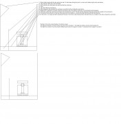
Pixels from
1, 1
1, 2
1, 3
1, 4
1, 5
1, 6
1, 7
Each of these 7 pixels have a optical device that splits the pixels light into 74 projected beams of light.
So 7 pixels is 28 beams of light.
The light from the pixel is only visible where the light is projected.
The divergence angle is made small by using a optical system on the TV. By the divergence angle being made small the light sent from the pixel to the eye remains a small radius of light.
A example of a small divergence angle is a laser pens light beam.
If this means only lasers can be used, then that is the situation.
• The theory is the pixel is surrounded by a box and the top of the box has a Plane Mirror that receives the light from the pixel.
• A glass pane is inbetween the Plane mirror that recieves the light from the pixel and the Plane mirror that redirects the light to different areas: if that light needs to be collimated.
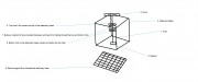
• This light then goes from the Plane mirror that receives the light from the pixel or from the glass pane onto another Plane mirror. This Plane mirror reflects the light upwards, onto the eye.
This plane mirror the redirects the light upward to the viewer is attached to a pole. The pole is attached to a base. The opposite end of the pole has been magnetized and this is how the pole moves, via magnetic force.
The base that holds the pole is lined with electromagnets that become magnetized with electricity. When electricity flows into the magnet, the pole moves, and so the mirror that is attached to the pole is moved.
It functions like a coffee swizzle stick stirring coffee.
_______
• The glass pane needs to be close to the reflection from the Plane mirror.
When a light beam is widening, the glass pane that collimates the light may be too far so that when the light is collimated the beam it is already wide: the glass pane needs to be close to the Plane mirror.
With no glass pane then if the light going into the Plane mirror was widening, it will be a very wide light beam when it gets beamed to the viewer.
The thickness of the glass pane makes different collimated beams. The more thick the glass pane the more it collimates the light beam.
If you need a large divergent angle from a widening beam of light, then make the glass pane thin or use only one thin one.
• The divergent beams of light can be separated because they have different trajectories.
I have successfully split three beams of light, and cleanly projected it on my ceiling.
The light source was a LED night light, the push to power on type - there were three LED white lights in there.
When it's powered on it shines a single light source from all the beams being so wide they blend into each other.
I used ordinary mirrors instead of a plane mirrors, and on top of the second set of mirrors glass panes.
So the light from the led went to mirrors having a large wide beam, then to the second mirrors then up and through the glass panes to the ceiling.
Doing this showed three squares of light spaced evenly apart. The process collimated the beams of light the LED sent.
When I blocked light from the led so only two led lights shone, the ceiling only showed two lights - 2 per glass pane, one glass pane over every mirror.
When I blocked two lights from shining from the led the ceiling only showed only light square per glass pane.
So you can take beams of light that are close to each other and have wide beams that blend into each other and cleanly divide and collimate them.
• I asked somebody over at physicsforums.com how to calculate the brightness through the aperture and they said:
"If the beam is collimated and if the beam is uniformally illuminated then the brightness will depend on the area of the aperture that the beam goes through."
Link
_______
I envision a robotic engineer will make a robot, and this robot will control the direction the Plane Mirrors shines light, so from light from the pixel will shine onto the eye of the viewer.
The TV's resolution is split into two, with half of the pixels being used for the left eye and half for the right eye.
The optical system above the pixel covers the entire light being emitted by the pixel, so no other pixel receives light from this pixel.
This way the light from the pixel is only sent to the first set of mirrors.
_______
Summary
Current lenticular lens autostereoscopic TV acts similarly to a LCD Polarizer. That is the divergence angle of the light beam is shared, so there is only unseparated light beams.
The single light beam isn't focused to one spot like a laser pens beam.
If different people can see the same light light beam for the left and right eye, then how can the eyes of these people divide the light so the eye only see's the light beam it was supposed to?
My idea is
• have the Light split into multiple beams - from the Pixel to the 4 Plane mirrors above the pixel - each Plane mirror captures 20% of the light from the pixel,
• kept in a small divergence angle - the size of the pixel by being collimated by running through the glass panes, this step may be unnecessary since a pixels light is already collimated,
• sent to a specific coordinate - the left or right eye - after the light is collimated it has a small divergence angle so then only the left or right eye of the one person receives the light it sent. What sends the light is a redirectable plane mirror sending a reflection to the eye of the viewer(s), this guidance is done via robot, so the beam from the plane mirrors follows the viewers eyes using a mechanical device.
• Caveat Emptor: Laser beams can have this collimated beam, but may burn the eye.
• The result is time parallel projection of a stereoscopic image to seven viewers each seeing full resolution of the TV.
The display may switch from 3D to 2D if the source sends both eyes the same image, which would not be stereoscopic.
The display may be 2D, 3D autostereoscopic, or 3D Volumetric.
Each depends on how the left right eye is seeing the beams of light.
• Volumetric: the beams of light are viewable per mm to the left or right, each new mm shows a unique pov. The limit to the mm is the focal points made possible by the number of mirrors above the pixel.
• Stereoscopic: the mirrors show the same pixel to seven peoples pov of the display, so each recieves the light from the displays pixels and they all see the same stereoscopic picture.
• 2D: the stereoscopic image is made by sending the light to both eyes so the light is different in each eye. 2D sends the same light to both eyes.
[youtube]http://www.youtube.com/watch?v=hfbEvqohkEQ[/youtube]
About the video:
• There is no eye tracking, also there is no 3D volumetric video source.
• How the hologram is supposed to work is the eye tracking follows the eyes, and when the eyes move a millimeter to the left or right, up or down the picture of pixel being shown by my optical system changes.
So the eyes move a millimeter to the left then the volumetric 3D picture shows the picture from that viewing angle which is a different picture than what was seen before.
Also the demonstration video was not a stereoscopic pair, but a 2D source video intended to only show the concept and how effective the concept is.
I'm not patenting this. I'm hoping somebody will put it to good use for a 3D system though.
I'm posting this here to get feedback and maybe somebody can patent this and run with it to see how far they can take this design I made? All I ask is I get credit to Jeremy Duncan, me.
1, 1
1, 2
1, 3
1, 4
1, 5
1, 6
1, 7
Each of these 7 pixels have a optical device that splits the pixels light into 74 projected beams of light.
So 7 pixels is 28 beams of light.
The light from the pixel is only visible where the light is projected.
The divergence angle is made small by using a optical system on the TV. By the divergence angle being made small the light sent from the pixel to the eye remains a small radius of light.
A example of a small divergence angle is a laser pens light beam.
If this means only lasers can be used, then that is the situation.
• The theory is the pixel is surrounded by a box and the top of the box has a Plane Mirror that receives the light from the pixel.
• A glass pane is inbetween the Plane mirror that recieves the light from the pixel and the Plane mirror that redirects the light to different areas: if that light needs to be collimated.
• This light then goes from the Plane mirror that receives the light from the pixel or from the glass pane onto another Plane mirror. This Plane mirror reflects the light upwards, onto the eye.
This plane mirror the redirects the light upward to the viewer is attached to a pole. The pole is attached to a base. The opposite end of the pole has been magnetized and this is how the pole moves, via magnetic force.
The base that holds the pole is lined with electromagnets that become magnetized with electricity. When electricity flows into the magnet, the pole moves, and so the mirror that is attached to the pole is moved.
It functions like a coffee swizzle stick stirring coffee.
_______
• The glass pane needs to be close to the reflection from the Plane mirror.
When a light beam is widening, the glass pane that collimates the light may be too far so that when the light is collimated the beam it is already wide: the glass pane needs to be close to the Plane mirror.
With no glass pane then if the light going into the Plane mirror was widening, it will be a very wide light beam when it gets beamed to the viewer.
The thickness of the glass pane makes different collimated beams. The more thick the glass pane the more it collimates the light beam.
If you need a large divergent angle from a widening beam of light, then make the glass pane thin or use only one thin one.
• The divergent beams of light can be separated because they have different trajectories.
I have successfully split three beams of light, and cleanly projected it on my ceiling.
The light source was a LED night light, the push to power on type - there were three LED white lights in there.
When it's powered on it shines a single light source from all the beams being so wide they blend into each other.
I used ordinary mirrors instead of a plane mirrors, and on top of the second set of mirrors glass panes.
So the light from the led went to mirrors having a large wide beam, then to the second mirrors then up and through the glass panes to the ceiling.
Doing this showed three squares of light spaced evenly apart. The process collimated the beams of light the LED sent.
When I blocked light from the led so only two led lights shone, the ceiling only showed two lights - 2 per glass pane, one glass pane over every mirror.
When I blocked two lights from shining from the led the ceiling only showed only light square per glass pane.
So you can take beams of light that are close to each other and have wide beams that blend into each other and cleanly divide and collimate them.
• I asked somebody over at physicsforums.com how to calculate the brightness through the aperture and they said:
"If the beam is collimated and if the beam is uniformally illuminated then the brightness will depend on the area of the aperture that the beam goes through."
Link
_______
I envision a robotic engineer will make a robot, and this robot will control the direction the Plane Mirrors shines light, so from light from the pixel will shine onto the eye of the viewer.
The TV's resolution is split into two, with half of the pixels being used for the left eye and half for the right eye.
The optical system above the pixel covers the entire light being emitted by the pixel, so no other pixel receives light from this pixel.
This way the light from the pixel is only sent to the first set of mirrors.
_______
Summary
Current lenticular lens autostereoscopic TV acts similarly to a LCD Polarizer. That is the divergence angle of the light beam is shared, so there is only unseparated light beams.
The single light beam isn't focused to one spot like a laser pens beam.
If different people can see the same light light beam for the left and right eye, then how can the eyes of these people divide the light so the eye only see's the light beam it was supposed to?
My idea is
• have the Light split into multiple beams - from the Pixel to the 4 Plane mirrors above the pixel - each Plane mirror captures 20% of the light from the pixel,
• kept in a small divergence angle - the size of the pixel by being collimated by running through the glass panes, this step may be unnecessary since a pixels light is already collimated,
• sent to a specific coordinate - the left or right eye - after the light is collimated it has a small divergence angle so then only the left or right eye of the one person receives the light it sent. What sends the light is a redirectable plane mirror sending a reflection to the eye of the viewer(s), this guidance is done via robot, so the beam from the plane mirrors follows the viewers eyes using a mechanical device.
• Caveat Emptor: Laser beams can have this collimated beam, but may burn the eye.
• The result is time parallel projection of a stereoscopic image to seven viewers each seeing full resolution of the TV.
The display may switch from 3D to 2D if the source sends both eyes the same image, which would not be stereoscopic.
The display may be 2D, 3D autostereoscopic, or 3D Volumetric.
Each depends on how the left right eye is seeing the beams of light.
• Volumetric: the beams of light are viewable per mm to the left or right, each new mm shows a unique pov. The limit to the mm is the focal points made possible by the number of mirrors above the pixel.
• Stereoscopic: the mirrors show the same pixel to seven peoples pov of the display, so each recieves the light from the displays pixels and they all see the same stereoscopic picture.
• 2D: the stereoscopic image is made by sending the light to both eyes so the light is different in each eye. 2D sends the same light to both eyes.
[youtube]http://www.youtube.com/watch?v=hfbEvqohkEQ[/youtube]
About the video:
• There is no eye tracking, also there is no 3D volumetric video source.
• How the hologram is supposed to work is the eye tracking follows the eyes, and when the eyes move a millimeter to the left or right, up or down the picture of pixel being shown by my optical system changes.
So the eyes move a millimeter to the left then the volumetric 3D picture shows the picture from that viewing angle which is a different picture than what was seen before.
Also the demonstration video was not a stereoscopic pair, but a 2D source video intended to only show the concept and how effective the concept is.
I'm not patenting this. I'm hoping somebody will put it to good use for a 3D system though.
I'm posting this here to get feedback and maybe somebody can patent this and run with it to see how far they can take this design I made? All I ask is I get credit to Jeremy Duncan, me.