Pixels from
1, 1
1, 2
1, 3
1, 4
1, 5
1, 6
1, 7
Each of these 7 pixels have a optical device that splits the pixels light into 74 projected beams of light.
So 7 pixels is 28 beams of light.
The light from the pixel is only visible where the light is projected.
The divergence angle is made small by using a optical system on the TV. By the divergence angle being made small the light sent from the pixel to the eye remains a small radius of light.
A example of a small divergence angle is a laser pens light beam.
If this means only lasers can be used, then that is the situation.
• The theory is the pixel is surrounded by a box and the top of the box has a Plane Mirror that receives the light from the pixel.
• A glass pane is inbetween the Plane mirror that recieves the light from the pixel and the Plane mirror that redirects the light to different areas: if that light needs to be collimated.
• This light then goes from the Plane mirror that receives the light from the pixel or from the glass pane onto another Plane mirror. This Plane mirror reflects the light upwards, onto the eye.
This plane mirror the redirects the light upward to the viewer is attached to a pole. The pole is attached to a base. The opposite end of the pole has been magnetized and this is how the pole moves, via magnetic force.
The base that holds the pole is lined with electromagnets that become magnetized with electricity. When electricity flows into the magnet, the pole moves, and so the mirror that is attached to the pole is moved.
It functions like a coffee swizzle stick stirring coffee.
_______
• The glass pane needs to be close to the reflection from the Plane mirror.
When a light beam is widening, the glass pane that collimates the light may be too far so that when the light is collimated the beam it is already wide: the glass pane needs to be close to the Plane mirror.
With no glass pane then if the light going into the Plane mirror was widening, it will be a very wide light beam when it gets beamed to the viewer.
The thickness of the glass pane makes different collimated beams. The more thick the glass pane the more it collimates the light beam.
If you need a large divergent angle from a widening beam of light, then make the glass pane thin or use only one thin one.
• The divergent beams of light can be separated because they have different trajectories.
I have successfully split three beams of light, and cleanly projected it on my ceiling.
The light source was a LED night light, the push to power on type - there were three LED white lights in there.
When it's powered on it shines a single light source from all the beams being so wide they blend into each other.
I used ordinary mirrors instead of a plane mirrors, and on top of the second set of mirrors glass panes.
So the light from the led went to mirrors having a large wide beam, then to the second mirrors then up and through the glass panes to the ceiling.
Doing this showed three squares of light spaced evenly apart. The process collimated the beams of light the LED sent.
When I blocked light from the led so only two led lights shone, the ceiling only showed two lights - 2 per glass pane, one glass pane over every mirror.
When I blocked two lights from shining from the led the ceiling only showed only light square per glass pane.
So you can take beams of light that are close to each other and have wide beams that blend into each other and cleanly divide and collimate them.
• I asked somebody over at physicsforums.com how to calculate the brightness through the aperture and they said:
"If the beam is collimated and if the beam is uniformally illuminated then the brightness will depend on the area of the aperture that the beam goes through."
Link
_______
I envision a robotic engineer will make a robot, and this robot will control the direction the Plane Mirrors shines light, so from light from the pixel will shine onto the eye of the viewer.
The TV's resolution is split into two, with half of the pixels being used for the left eye and half for the right eye.
The optical system above the pixel covers the entire light being emitted by the pixel, so no other pixel receives light from this pixel.
This way the light from the pixel is only sent to the first set of mirrors.
_______
Summary
Current lenticular lens autostereoscopic TV acts similarly to a LCD Polarizer. That is the divergence angle of the light beam is shared, so there is only unseparated light beams.
The single light beam isn't focused to one spot like a laser pens beam.
If different people can see the same light light beam for the left and right eye, then how can the eyes of these people divide the light so the eye only see's the light beam it was supposed to?
My idea is
• have the Light split into multiple beams - from the Pixel to the 4 Plane mirrors above the pixel - each Plane mirror captures 20% of the light from the pixel,
• kept in a small divergence angle - the size of the pixel by being collimated by running through the glass panes, this step may be unnecessary since a pixels light is already collimated,
• sent to a specific coordinate - the left or right eye - after the light is collimated it has a small divergence angle so then only the left or right eye of the one person receives the light it sent. What sends the light is a redirectable plane mirror sending a reflection to the eye of the viewer(s), this guidance is done via robot, so the beam from the plane mirrors follows the viewers eyes using a mechanical device.
• Caveat Emptor: Laser beams can have this collimated beam, but may burn the eye.
• The result is time parallel projection of a stereoscopic image to seven viewers each seeing full resolution of the TV.
The display may switch from 3D to 2D if the source sends both eyes the same image, which would not be stereoscopic.
The display may be 2D, 3D autostereoscopic, or 3D Volumetric.
Each depends on how the left right eye is seeing the beams of light.
• Volumetric: the beams of light are viewable per mm to the left or right, each new mm shows a unique pov. The limit to the mm is the focal points made possible by the number of mirrors above the pixel.
• Stereoscopic: the mirrors show the same pixel to seven peoples pov of the display, so each recieves the light from the displays pixels and they all see the same stereoscopic picture.
• 2D: the stereoscopic image is made by sending the light to both eyes so the light is different in each eye. 2D sends the same light to both eyes.
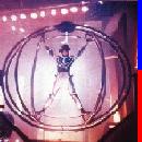
[youtube]http://www.youtube.com/watch?v=hfbEvqohkEQ[/youtube]
About the video:
• There is no eye tracking, also there is no 3D volumetric video source.
• How the hologram is supposed to work is the eye tracking follows the eyes, and when the eyes move a millimeter to the left or right, up or down the picture of pixel being shown by my optical system changes.
So the eyes move a millimeter to the left then the volumetric 3D picture shows the picture from that viewing angle which is a different picture than what was seen before.
Also the demonstration video was not a stereoscopic pair, but a 2D source video intended to only show the concept and how effective the concept is.
I'm not patenting this. I'm hoping somebody will put it to good use for a 3D system though.
I'm posting this here to get feedback and maybe somebody can patent this and run with it to see how far they can take this design I made? All I ask is I get credit to Jeremy Duncan, me.
Autostereoscopic technology: I show you my device Design
-
JDuncan
- Cross Eyed!
- Posts: 130
- Joined: Wed Feb 09, 2011 3:30 pm
- Location: My Left Hand
- Contact:
Autostereoscopic technology: I show you my device Design
You do not have the required permissions to view the files attached to this post.
-
cybereality

- 3D Angel Eyes (Moderator)
- Posts: 11407
- Joined: Sat Apr 12, 2008 8:18 pm
Re: Autostereoscopic technology: I show you my device Design
Hmm, this sounds pretty interesting. I am not sure I understand the concept completely, but I understand enough to believe it could work. I guess this would be considered a "Directed Light Control" system like the auto-stereo display on the Fujifilm W1 camera. However with the W1 only the backlight is modulated, there is no reflection of light like with your idea. I watched the whole video and I am not exactly sure what it proves. What I see is that you are reflecting the light from a phone screen off of 2 mirrors. I would assume this to be possible, it still doesn't address the source of light (ie that cellphone screen is not bright enough to project onto the ceiling like the laser can). So it seems like it would still require a projector, although there are laser pico projectors available for cheap, so I guess this is not a issue.
What I still don't get is if this is a full-resolution or interlaced solution. You seems to suggest both things. Cause from what I am getting, it could be a full resolution solution. If you could properly collimate the light in such a way that it was only visible in a narrow angle, then you should be able to use just one moving mirror and have a full resolution 3D image, right? Naturally you would need some mechanics (servo?) that could oscillate with at least 60Hz (ideally at 120Hz or greater) so that it could direct the light to either of your eyes. If it were an interlaced solution than this would require an array of hundreds of little mirrors, but at that point it is basically a lenticular method, I am not sure what the advantage over lenticular would be (or why you even need moving parts).
The last thing I don't get is how you can take a single pixel (3 sub-pixel components or RGB) and split it into unique elements. There are only 3 color components which result in a single perceived color. How are you generating more than a single color from one pixel? You either split it spatially (ie film patterned retarder, lenticular) or temporally (active shutter glasses) and it is not clear which one you are doing (or are you doing both?). So upon further review I am not exactly sure how this is working (or if it is even working at all). But I believe!
-
JDuncan
- Cross Eyed!
- Posts: 130
- Joined: Wed Feb 09, 2011 3:30 pm
- Location: My Left Hand
- Contact:
Re: Autostereoscopic technology: I show you my device Design
It uses a lot of mirrors and doesn't oscillate a mirror at 60 Hz. Each of the mirrors is aimed at the eye, either the left or right eye, and only moves to send the light to the eye when the persons head moves.
So by your definition, it's interlaced/lenticular.
It (the mirror) needs to move so that the image sent by the mirror can be redirected. One mirror sends the light to the other mirror and only one of these mirrors needs to move so that the person can see the image from that moving mirror when they move their head.
This enables volumetic 3D images to be viewed or stereoscopic 3D, depending on the image source.
The mirror would be above the three sub pixels that make up the pixel. So each of the sub pixels would fit into one optical box.
Because it can show the same pixel to many eyes, the length of the pixel may have to be long so it can span many mirrors, one mirror set for one eye.
-
tritosine5G

- Terrif-eying the Ladies!
- Posts: 894
- Joined: Wed Mar 17, 2010 9:35 am
- Location: As far from Hold Display guys as possible!!! ^2
Re: Autostereoscopic technology: I show you my device Design
ultra hi res laser projectors already exist for 250k -500k dollars .
http://www.projectorcentral.com/Evans_& ... P_8K-5.htm" onclick="window.open(this.href);return false;
http://www.projectorcentral.com/Evans_& ... P_8K-5.htm" onclick="window.open(this.href);return false;
-Biased for 0 Gen HMD's to hell and back must be one hundred percent hell bent bias!
-
JDuncan
- Cross Eyed!
- Posts: 130
- Joined: Wed Feb 09, 2011 3:30 pm
- Location: My Left Hand
- Contact:
Re: Autostereoscopic technology: I show you my device Design
I'll attach a Patent Diagram Rough sketch. You would give this to the person making the patent illustration and he would draw you a good copy for your patent application.
You do not have the required permissions to view the files attached to this post.
-
cybereality
- 3D Angel Eyes (Moderator)
- Posts: 11407
- Joined: Sat Apr 12, 2008 8:18 pm
Re: Autostereoscopic technology: I show you my device Design
So fundamentally this is a similar technique to lenticular 3D. I mean, if you are using an array of mirrors the height of the display in order to redirect light, then this is almost exactly what the lenticles are doing in a lenticular setup. Having the mirrors motorized, is different, and syncing this with a head-tracking mechanism is interesting. However, you could achieve the same exact effect without any moving parts at all and far simpler. For example, you could use a parallax barrier (like the DIY one I made: http://www.mtbs3d.com/phpBB/viewtopic.p ... 961#p55961" onclick="window.open(this.href);return false; ) then have a webcam (or other tracking mechanism) to track the users eyes. Then all you would have to do is alter the interleaved pattern on the screen to account of the users position to avoid pseudo-stereo. You could also use this data to rotate the angle on the view in order to fake a volumetric/holographic effect. So this could be done without moving parts and for less than $50. I actually plan on working on this myself, but there is only so much time in the day.
-
AntiCatalyst
- Cross Eyed!
- Posts: 168
- Joined: Tue Jan 25, 2011 7:53 pm
- Location: Sweden
Re: Autostereoscopic technology: I show you my device Design
this seems to be autostereoscopic for multiple viewers.
light loss would be tremendous though, and you'd have to build over 2 million of these "boxes" for a single half-resolution fullHD screen.
light loss would be tremendous though, and you'd have to build over 2 million of these "boxes" for a single half-resolution fullHD screen.

"This is great!"
-
JDuncan
- Cross Eyed!
- Posts: 130
- Joined: Wed Feb 09, 2011 3:30 pm
- Location: My Left Hand
- Contact:
Re: Autostereoscopic technology: I show you my device Design
To do what cybereality suggests, use this pattern. you have the ideal sweet spot, and then what moving the head does to this ideal sweet spot. Then you recreate the sweet spot using head tracking and alter the interleaved pattern to match the new sweet spot position.
A way I saw this could be done is a wedge prism method. This is where two prisms are stacked and by moving the prisms position the light they steer changes direction.
Instead of using wedge prisms you would use parallax barrier sheets, and one sheet is motorized so when you move your head you use a remote control and it shifts one parallax barrier sheet to the left or right and then the light steered by the sheets is sent to a new position. But this is if you stay in the same distance from the TV but you move to the left or right.
Or if you use the monitor then the image would shift to the left or right.
To change the sweet spot to match distance then the image sent by the monitor would have to be made to match that new distance, and this is different then just shifting the image to the left or right.
If there was a player that automatically shifted the image on the screen to the left or right via remote control something like mpc or zoom player then that would be cool and it would work, I'm not sure how you will end up shifting the image sent by the screen.
And to AntiCatalyst, yes my solution is for multiple viewers viewing autostereoscopic image. Building it seems reasonable, it's not a overly complex design or a complicated theory.
Edit,
Back to what I wrote about the parallax barrier sheet method. To use sw and the webcam so you can get eye tracking, and only one parallax barrier sheet: you would have a chart table. This chart table shows that at distance x, y, z from the ideal sweet spot, then the image displayed would be altered in that specific manner so you see 3D where your eyes are.
Then the webcam works with the chart table so the display sends 3D properly.
-
cybereality
- 3D Angel Eyes (Moderator)
- Posts: 11407
- Joined: Sat Apr 12, 2008 8:18 pm
Re: Autostereoscopic technology: I show you my device Design
Well with my parallax barrier idea you cannot ever move in the z axis (forward or back). Tracking would only work from left to right within a certain sweet-zone (maybe 1 meter wide). With your idea it seems possible for z axis tracking and adjustment, in addition to wider viewing angles. However the whole setup seems really complicated and probably not possible for a hobbyist to complete in his garage.
-
AntiCatalyst
- Cross Eyed!
- Posts: 168
- Joined: Tue Jan 25, 2011 7:53 pm
- Location: Sweden
Re: Autostereoscopic technology: I show you my device Design
i think each pixel uses a separate set of mirrors, so it's not at all like lenticular. It's more like each and every pixel can mirror its light to multiple separate dynamic angles. It IS very complicated, and impossible to DIY anything else than a proof-of-concept display with a few pixels.
btw cybereality, I think the Fujifilm autostereo-display is basically just an auto-adjusting parallax barrier, but with the barrier located in between the LCD and the backlight diffuser. Since LCD's are transparent, this works exactly the same way as your DIY solution, but the critical parts are well protected inside the display.
btw cybereality, I think the Fujifilm autostereo-display is basically just an auto-adjusting parallax barrier, but with the barrier located in between the LCD and the backlight diffuser. Since LCD's are transparent, this works exactly the same way as your DIY solution, but the critical parts are well protected inside the display.
"This is great!"
-
cybereality
- 3D Angel Eyes (Moderator)
- Posts: 11407
- Joined: Sat Apr 12, 2008 8:18 pm
Re: Autostereoscopic technology: I show you my device Design
I believe the Fujifilm display is using a "Directed Light Control" system to achieve the effect. So what they have is a special backlight that can modulate between two angles of carefully collimated light. Then there is also a monochrome LCD active parallax barrier behind the color LCD panel. The parallax barrier switches interleaving in sync with the left/right backlight angle switching. So what you get is a mix between active shutter-glasses and passive interlaced, just without glasses. At least I think thats how it works. If not, maybe I should look into getting a patent on that idea...AntiCatalyst wrote: btw cybereality, I think the Fujifilm autostereo-display is basically just an auto-adjusting parallax barrier, but with the barrier located in between the LCD and the backlight diffuser. Since LCD's are transparent, this works exactly the same way as your DIY solution, but the critical parts are well protected inside the display.
-
JDuncan
- Cross Eyed!
- Posts: 130
- Joined: Wed Feb 09, 2011 3:30 pm
- Location: My Left Hand
- Contact:
Re: Autostereoscopic technology: I show you my device Design
Each pixel does have it's own set of of mirrors, and each mirror set can direct the light from the pixel to it's own ray: where the ray from the tv is visible.AntiCatalyst wrote:i think each pixel uses a separate set of mirrors, so it's not at all like lenticular. It's more like each and every pixel can mirror its light to multiple separate dynamic angles. It IS very complicated, and impossible to DIY anything else than a proof-of-concept display with a few pixels.
It is complicated to build, I admit, but the theory and design of the thing isn't complicated.
-
JDuncan
- Cross Eyed!
- Posts: 130
- Joined: Wed Feb 09, 2011 3:30 pm
- Location: My Left Hand
- Contact:
Re: Autostereoscopic technology: I show you my device Design
There's no delete button.
-
JDuncan
- Cross Eyed!
- Posts: 130
- Joined: Wed Feb 09, 2011 3:30 pm
- Location: My Left Hand
- Contact:
Re: Autostereoscopic technology: I show you my device Design
So I read the manual and wrote this patent:
specification, or description
Title of the invention.
"Autostereoscopic Projection viewer apparatus".
cross reference to related applications: "Not Applicable".
Statement Regarding Federally Sponsored Research or Development: "Not Applicable".
Reference to Sequence Listing, a Table, or a Computer Program Listing Compact Disc Appendix: "Not Applicable".
Background of the Invention.
Current lenticular lens autostereoscopic TV acts similarly to a LCD Polarizer. That is the divergence angle of the light beam is shared, so there is only unseparated light beams.
The single light beam isn't focused to one spot like a laser pens beam.
If different people can see the same light light beam for the left and right eye, then how can the eyes of these people divide the light so the eye only see's the light beam it was supposed to?
DLP TV's use MEM devices, or Microelectrical electrical mirrors, and DLP TV also use reflected light.
However these TV's have light with a large divergence angle, reflecting light in all directions.
Brief Summary of the Invention.
With my "Autostereoscopic Projection viewer apparatus", the divergence angle of the light is kept small, this is so that the light being sent by the viewer may be visible only to the single eye of the viewer.
The viewer uses MEMS like a dlp does but it uses Plane mirrors on the MEMS in order to keep the divergence angle of the light small, and bright.
So my Autostereoscopic Projection Viewer is a variation of a DLP TV.
Brief Description of the two Views of the Drawing.
FIG. 1 shows a general schematic of an autostereoscopic projection viewer.
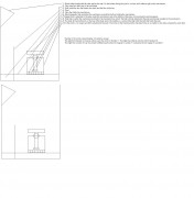
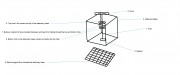
FIG. 2 shows a general schematic of an stationary base.
Detailed Description of the Invention.
The viewer is a extension of a display such as a crt, or plasma, or lcd, or dlp TV. It sits on the screen and is inbetween the display and the person watching the TV.
The display sends light into the viewer and the viewer redirects this light to the left and right eyes of the persons watching the TV by using reflection via MEMS mirrors within the viewer.
The viewer has two mirrors and one mechanical device that is in a box, and this box is directly over one pixel of the display so that the light from the pixel shines into the box.
The displays pixels light shines directly onto one of the mirrors facing it so that this mirror then reflects this pixels light onto the other mirror and this other mirror is facing the opposite direction and so reflecting light in that direction.
The mirror that is receiving the reflected light from the other mirror is attached to a mechanical device that allows the mirror to move and so change where the light it's reflecting is being sent to.
How the viewer is built the mirror facing the pixels light is above the mirror that it reflects light on.
The mechanical device is a stationary base that is hollow, and this base holds a moveable pole, the pole is held in the base by a bulbous center on the pole that fits into a socket on the top and middle of the hollow box base.
On the pole is three parts, the far left and right of the pole and the center: one far side holds a magnet, one far side holds a mirror, and the center is bulbous.
The magnet on the pole is within the hollow base but does not touch the bottom of the hollow base on the floor of the base of on the walls of the base; only the bulbous center on the pole touches the base.
The bulbous center on the pole is held in the socket by two windows on the top and bottom of the socket that the pole fits through; the windows can fit the pole through the window hole but not the bulbous center.
On the floor directly beneath the base is a grid matrix of electromagnets and each section of the grid can be activated apart from all the other grids, and when it actives so it's a active electromagnet it attracts the magnet on the pole, and in this manner the pole moves and so the mirror on the pole faces different directions.
On the display is a camera and the display has sw that can work with the camera so it knows the x, y, z location of the persons eyes as they watch the TV.
When the sw knows the location of the eyes it activates a electromagnet to point the light at that position, so all the pixels use the viewer to beam light to the left and right eyes of the person watching the TV.
The mirrors are Plane mirrors, but regular mems mirrors may work if they can be made to have a small divergence angle of light.
I envision the viewer and mechanical device can be made using lithography, but really I don't know for certain how it may be manufactured.
Light loss is about 25%, or 30% or the original light when it travels through the viewer in a test I did where I published the test, so you can watch the video and decide the light loss for yourself.
Also I don't know the sw or camera to be used, or how the sw would work specifically.
Claims:
The invention claimed is:
1. A Autostereoscopic Projection Viewer. Comprising: one projector viewer receiving light from a displays pixel, so every pixel in a TV display has it's own projector viewer.
A projectors viewer uses two Plane Mirrors to reflect light beams received from the pixel sending the reflected light to a predetermined eyezone. A predetermined eyezone is predetermined by a camera on the display tracking the eyezones x, y, z position relative to the projection viewer.
2. The viewer of claim 1, wherein said projector viewer receives light from the displays pixel. The light from the displays pixel shines directly onto one plane mirror the mirror then reflects this light onto the other plane mirror.
3. The viewer of claim 1, wherein said projector viewer includes a stationary base within the projector viewer. A stationary base holds a moveable pole with a magnet at one far end of the pole and one of the mirrors at the opposite end of the pole.
4. The viewer of claim 3, wherein said pole includes a bulbous center at the midpoint. A bulbous center on the pole is what attaches the pole to the stationary base at the top and middle of the stationary base allowing the pole to freely swivle circularly within the stationary base.
5. The viewer of claim 4, wherein the floor beneath said stationary base includes electromagnets. A electromagnet floor attracts the magnet on the pole and so directs the mirror on the pole to face different directions. The pole is only attached to the stationary base and does not touch the electromagnetic floor beneath the stationary base.
6. The viewer of claim 5, wherein the mirror is moved including the light reflected onto it by the other mirror which received it's light from the pixel. The mirror is moved to face in a specific direction and so reflects the light it receives there.
7. The stationary base of claim 3, wherein said projector viewer includes a socket within the stationary base. A socket located on the top and center of the stationary base holds the bulbous portion of the pole. The socket has two window holes above and below the socket that are smaller than the bulbous portion that is in the socket so that the bulbous portion does not fall through the top or bottom of the socket. A portion of the bulbous portion goes through the top and bottom window of the socket and is able to roll within the socket so that the pole may swivle in the socket circularly With little to no resistance.
Abstract of the Disclosure.
The present invention allows direct time parallel projection viewing of three dimensional (3D), two dimensional (2D), full color images that are capable of being viewed by the unaided human eye, i.e., without the requirement of viewing helmets, polaroid glasses, or other viewing aids.
specification, or description
Title of the invention.
"Autostereoscopic Projection viewer apparatus".
cross reference to related applications: "Not Applicable".
Statement Regarding Federally Sponsored Research or Development: "Not Applicable".
Reference to Sequence Listing, a Table, or a Computer Program Listing Compact Disc Appendix: "Not Applicable".
Background of the Invention.
Current lenticular lens autostereoscopic TV acts similarly to a LCD Polarizer. That is the divergence angle of the light beam is shared, so there is only unseparated light beams.
The single light beam isn't focused to one spot like a laser pens beam.
If different people can see the same light light beam for the left and right eye, then how can the eyes of these people divide the light so the eye only see's the light beam it was supposed to?
DLP TV's use MEM devices, or Microelectrical electrical mirrors, and DLP TV also use reflected light.
However these TV's have light with a large divergence angle, reflecting light in all directions.
Brief Summary of the Invention.
With my "Autostereoscopic Projection viewer apparatus", the divergence angle of the light is kept small, this is so that the light being sent by the viewer may be visible only to the single eye of the viewer.
The viewer uses MEMS like a dlp does but it uses Plane mirrors on the MEMS in order to keep the divergence angle of the light small, and bright.
So my Autostereoscopic Projection Viewer is a variation of a DLP TV.
Brief Description of the two Views of the Drawing.
FIG. 1 shows a general schematic of an autostereoscopic projection viewer.
FIG. 2 shows a general schematic of an stationary base.
Detailed Description of the Invention.
The viewer is a extension of a display such as a crt, or plasma, or lcd, or dlp TV. It sits on the screen and is inbetween the display and the person watching the TV.
The display sends light into the viewer and the viewer redirects this light to the left and right eyes of the persons watching the TV by using reflection via MEMS mirrors within the viewer.
The viewer has two mirrors and one mechanical device that is in a box, and this box is directly over one pixel of the display so that the light from the pixel shines into the box.
The displays pixels light shines directly onto one of the mirrors facing it so that this mirror then reflects this pixels light onto the other mirror and this other mirror is facing the opposite direction and so reflecting light in that direction.
The mirror that is receiving the reflected light from the other mirror is attached to a mechanical device that allows the mirror to move and so change where the light it's reflecting is being sent to.
How the viewer is built the mirror facing the pixels light is above the mirror that it reflects light on.
The mechanical device is a stationary base that is hollow, and this base holds a moveable pole, the pole is held in the base by a bulbous center on the pole that fits into a socket on the top and middle of the hollow box base.
On the pole is three parts, the far left and right of the pole and the center: one far side holds a magnet, one far side holds a mirror, and the center is bulbous.
The magnet on the pole is within the hollow base but does not touch the bottom of the hollow base on the floor of the base of on the walls of the base; only the bulbous center on the pole touches the base.
The bulbous center on the pole is held in the socket by two windows on the top and bottom of the socket that the pole fits through; the windows can fit the pole through the window hole but not the bulbous center.
On the floor directly beneath the base is a grid matrix of electromagnets and each section of the grid can be activated apart from all the other grids, and when it actives so it's a active electromagnet it attracts the magnet on the pole, and in this manner the pole moves and so the mirror on the pole faces different directions.
On the display is a camera and the display has sw that can work with the camera so it knows the x, y, z location of the persons eyes as they watch the TV.
When the sw knows the location of the eyes it activates a electromagnet to point the light at that position, so all the pixels use the viewer to beam light to the left and right eyes of the person watching the TV.
The mirrors are Plane mirrors, but regular mems mirrors may work if they can be made to have a small divergence angle of light.
I envision the viewer and mechanical device can be made using lithography, but really I don't know for certain how it may be manufactured.
Light loss is about 25%, or 30% or the original light when it travels through the viewer in a test I did where I published the test, so you can watch the video and decide the light loss for yourself.
Also I don't know the sw or camera to be used, or how the sw would work specifically.
Claims:
The invention claimed is:
1. A Autostereoscopic Projection Viewer. Comprising: one projector viewer receiving light from a displays pixel, so every pixel in a TV display has it's own projector viewer.
A projectors viewer uses two Plane Mirrors to reflect light beams received from the pixel sending the reflected light to a predetermined eyezone. A predetermined eyezone is predetermined by a camera on the display tracking the eyezones x, y, z position relative to the projection viewer.
2. The viewer of claim 1, wherein said projector viewer receives light from the displays pixel. The light from the displays pixel shines directly onto one plane mirror the mirror then reflects this light onto the other plane mirror.
3. The viewer of claim 1, wherein said projector viewer includes a stationary base within the projector viewer. A stationary base holds a moveable pole with a magnet at one far end of the pole and one of the mirrors at the opposite end of the pole.
4. The viewer of claim 3, wherein said pole includes a bulbous center at the midpoint. A bulbous center on the pole is what attaches the pole to the stationary base at the top and middle of the stationary base allowing the pole to freely swivle circularly within the stationary base.
5. The viewer of claim 4, wherein the floor beneath said stationary base includes electromagnets. A electromagnet floor attracts the magnet on the pole and so directs the mirror on the pole to face different directions. The pole is only attached to the stationary base and does not touch the electromagnetic floor beneath the stationary base.
6. The viewer of claim 5, wherein the mirror is moved including the light reflected onto it by the other mirror which received it's light from the pixel. The mirror is moved to face in a specific direction and so reflects the light it receives there.
7. The stationary base of claim 3, wherein said projector viewer includes a socket within the stationary base. A socket located on the top and center of the stationary base holds the bulbous portion of the pole. The socket has two window holes above and below the socket that are smaller than the bulbous portion that is in the socket so that the bulbous portion does not fall through the top or bottom of the socket. A portion of the bulbous portion goes through the top and bottom window of the socket and is able to roll within the socket so that the pole may swivle in the socket circularly With little to no resistance.
Abstract of the Disclosure.
The present invention allows direct time parallel projection viewing of three dimensional (3D), two dimensional (2D), full color images that are capable of being viewed by the unaided human eye, i.e., without the requirement of viewing helmets, polaroid glasses, or other viewing aids.
-
JDuncan
- Cross Eyed!
- Posts: 130
- Joined: Wed Feb 09, 2011 3:30 pm
- Location: My Left Hand
- Contact:
Re: Autostereoscopic technology: I show you my device Design
So somebody here said they want to do a patent. I watched a patent course on youtube and can tell you something about how to write a patent specification.
First the provisional patent needs a cover letter, fill this in and include the pictures and specification.
The specification includes all the bolded parts from my previous post, and the picture includes the pointing outof the parts of the inventiona dn numbering them.
The improtant part of a specification is the claims part and there is a special way to write claims.
There is mainly three parts.
These are: "A", "The", and the number of claims after this that reference previous claims numbers.
The first time you mention something it must use the word "A", and everytime that thing is referenced later on in other claims or later in that claim it references the thing that used the "A" word, and then you call it "The".
Example: claim 1.) A autostereoscopic viewer that uses the backlight of a display and lcd parallax barrier to direct light into a color lcd display so the person watching the display see's a 3D image. Claim 2.) the backlight and parallax barrier in claim one includes modulation. The backlight modulates the light sent to the lcd parallax barrier so the parallax barrier sends light to the color display and this light is visible only to one eye at a time.
I watched a patent course and new and non-obvious was defined as such:
New: means something that is created and not based on previous invention, so that your creating something that is not a improvement.
- My invention is based on DLP, but DLP does not stream a ray of light to a single eye so only that eye see's the light from that ray - DLP has the light visible in all directions. So my invention has no improvement to be based on since there is no DLP or autostereoscopic device that does this.
That is why I used only two mirrors so a single ray of light from the viewer is visible. That way it's not based on a device patent that does this with only two mirrors, so any following patents that use more mirrors for more views from a pixel are based on this patent that only uses two mirrors.
Obvious: means that it joins two inventions together to build a third invention, and putting the two parts together is so simple it requires no skill.
- Right now no autostereoscopic device streams a ray to a single eye so this is not from some other invention.
So with this said my invention is new and non-obvious.
-
cybereality
- 3D Angel Eyes (Moderator)
- Posts: 11407
- Joined: Sat Apr 12, 2008 8:18 pm
Re: Autostereoscopic technology: I show you my device Design
Ok cool. I was thinking about getting a patent but by the time I actually have the money to implement something like that I bet the patent would run out.
-
Dom
- Diamond Eyed Freakazoid!
- Posts: 824
- Joined: Sun Oct 19, 2008 12:30 pm
- Contact:
Re: Autostereoscopic technology: I show you my device Design
Its in your best interest to try and get a patent for all your inventions! What you can do with a patent is use it as a source of deposit for a start up company and you could get venture capital. I know this because I have a company called Zebrita Technologies, its just a home office right now and I am trying to develop over 10 products. I did try and get a patent and hired a patent lawyer. If you have a patent definently call a lawyer and see how they can help you even if it would cost 4000 dollars. Especially if you don't know how to format your patent cause that will make it denied. This is my patent I applied for and I did get it updated but eh I could not afford to do much more with it and getting venture capital is alot harder for me than i thought. So I now mainly give my ideas out for free. 
http://brevets-patents.ic.gc.ca/opic-ci ... ber_search" onclick="window.open(this.href);return false;
I am trying to make a holographic 3dtv, although my workings are alot different than whats been working on by scientists and proffesionals. I hope someone can make this if not me. And as long as VR and stereo3d moves forward thats all that matters, not the money you could make from ideas and inventions.
http://www.cns-nynolyt.com/files/doms-systemspecs.html My System specs In HTML
Cyberia on Youtube
__________________________________________________________________________________________
Cyberia on Youtube
__________________________________________________________________________________________