Hi,
A comment on my last blog post ( http://www.wastedspace.co.uk/cms/2011/0 ... t-part-12/ )made me see the light, and rather than fight the man to recreate what has been, to create something fresh with what is available now.
I am in the final stages of completing a build of an HD head mounted display, very much along the lines of this:
http://www.cyclopital3d.com/3DPhotoView ... anchor_120
Only much much lighter and using vitrolight 5.6" 1280X800 displays for each eye, front surface mirrors and a 2 Lens Convex Achromat 50mm +182.8mm lens for each eye.
Preliminary testing has gone exceedingly well.
I think inverting one of the screens and using IZ3D stereo mirror mode 3 or 4 should do it.
I got the idea, since affordable HD screens are too large to have side by side on your face, and a rig like this one: http://www.funsci.com/fun3_en/stscp/stscp.htm , with the extra mirrors would require substantial additional magnification, which would also require greater engineering precision.
I'll update my blog following successful (or not!) build.
But any interim comments prior to me bolting and gluing would be appreciated!
Cheers
Zach
( Edited title to reflect fact that it isn't a stereo-mirror per se. )
Stereo HMD using mirrors
-
zacherynuk

- Binocular Vision CONFIRMED!
- Posts: 296
- Joined: Sun Oct 03, 2010 2:56 pm
- Location: England
-
ShaneW
- One Eyed Hopeful
- Posts: 8
- Joined: Fri Sep 24, 2010 5:39 pm
Re: Stereo HMD using mirrors
Definitely an interesting idea, I just ordered another one of vitrolights 5.6" displays, a 4.8" display and 2 3.5" displays to fool around with. Let us know how it turns out! I was thinking of doing something along those lines with the 3.5" displays I ordered, either that or use some LEEP style optics in lieu of a folded design.
For two 4.8 or 5.6" displays that seems like a good way to go though!
For two 4.8 or 5.6" displays that seems like a good way to go though!
-
3dvison
- Diamond Eyed Freakazoid!
- Posts: 718
- Joined: Sun Oct 24, 2010 7:25 pm
Re: Stereo HMD using mirrors
Can't wait to see it zacherynuk.
Do you know what the FOV will be ? Could it be a large FOV like 60+ ?
Do you know what the FOV will be ? Could it be a large FOV like 60+ ?
-
cybereality

- 3D Angel Eyes (Moderator)
- Posts: 11407
- Joined: Sat Apr 12, 2008 8:18 pm
Re: Stereo HMD using mirrors
Yeah, I think mirrors are an essential tool for this type of thing. I hope it goes well.
-
zacherynuk
- Binocular Vision CONFIRMED!
- Posts: 296
- Joined: Sun Oct 03, 2010 2:56 pm
- Location: England
Re: Stereo HMD using mirrors
3dvison wrote:Can't wait to see it zacherynuk.
Do you know what the FOV will be ? Could it be a large FOV like 60+ ?
Hold a 75mmX125MM picture 80mm from you eyes
-
PalmerTech
- Golden Eyed Wiseman! (or woman!)
- Posts: 1644
- Joined: Fri Aug 21, 2009 9:06 pm
Re: Stereo HMD using mirrors
I had thought of doing this, but one possible issue: Will you be able to get the IPD right? It seems to be that you will have to cut off part of each screen's view to achieve this. Not a huge deal, but something to consider.
Back when I first wanted to try this, the IZ3D drivers did not support anything but vertical flip. I see this is not the case now, which is fantastic! Wish I had noticed earlier.
Oh! One more thought: Have you thought about housing the control board in a separate controller box, and just using really long LVDS cables from the control board to the panel? It should work for reasonably long distances, and would let you offload a lot of weight.
-
zacherynuk
- Binocular Vision CONFIRMED!
- Posts: 296
- Joined: Sun Oct 03, 2010 2:56 pm
- Location: England
Re: Stereo HMD using mirrors
IPD is fine, the two units will be mounted to the VR4 frame and will offer similar IPD adjustment to which we all have become acustomed. Also since lenses are 50mm, makes life easier.PalmerTech wrote:I had thought of doing this, but one possible issue: Will you be able to get the IPD right? It seems to be that you will have to cut off part of each screen's view to achieve this. Not a huge deal, but something to consider.
Back when I first wanted to try this, the IZ3D drivers did not support anything but vertical flip. I see this is not the case now, which is fantastic! Wish I had noticed earlier.
Oh! One more thought: Have you though about housing the control board in a separate controller box, and just using really long LVDS cables from the control board to the panel? It should work for reasonably long distances, and would let you offload a lot of weight.
Yup, LVDS cable will be extended using CAT6, only the 60g screens will be up front. The plastic housings and lenses weigh more at this time!
I'm probably not gonna get much of a chance to finish this until later next week as I am off skiing... but will update.
-
PalmerTech
- Golden Eyed Wiseman! (or woman!)
- Posts: 1644
- Joined: Fri Aug 21, 2009 9:06 pm
Re: Stereo HMD using mirrors
I meant more along the lines of the middle of the screens matching up to the middle of the eyes. Or will you be spacing the displays far enough away from the mirror for the entire LCD to be visible to the eye? I might not be making much sense here, I am far too tired to be wasting your time with what are probably obvious questions. 
-
Okta

- Golden Eyed Wiseman! (or woman!)
- Posts: 1515
- Joined: Tue Feb 12, 2008 5:22 am
Re: Stereo HMD using mirrors
What will be displayed in windows before you start a game with iz3d? One screen ok and the other reversed?
"I did not chip in ten grand to seed a first investment round to build value for a Facebook acquisition."
Notch on the FaceDisgrace buyout.
Notch on the FaceDisgrace buyout.
-
zacherynuk
- Binocular Vision CONFIRMED!
- Posts: 296
- Joined: Sun Oct 03, 2010 2:56 pm
- Location: England
Re: Stereo HMD using mirrors
It'll be a PITA, one screen will be inverted and reversed, one will be reversed!Okta wrote:What will be displayed in windows before you start a game with iz3d? One screen ok and the other reversed?
However I can run 3 monitors from this graphics card, so it's not the end of the world. If all goes to plan, I may see if I can get cheap enough analogue signal inverters and use analogue VGA splitter box to power the HMD...
Signalling is currently least of my worries
-
Okta
- Golden Eyed Wiseman! (or woman!)
- Posts: 1515
- Joined: Tue Feb 12, 2008 5:22 am
Re: Stereo HMD using mirrors
Check out my second post in this page http://www.mtbs3d.com/phpBB/viewtopic.p ... 2&start=30" onclick="window.open(this.href);return false;
Its a bit fancy but you have most of the gear to have a play with and wont need to correct the orientations.
Its a bit fancy but you have most of the gear to have a play with and wont need to correct the orientations.
"I did not chip in ten grand to seed a first investment round to build value for a Facebook acquisition."
Notch on the FaceDisgrace buyout.
Notch on the FaceDisgrace buyout.
-
zacherynuk
- Binocular Vision CONFIRMED!
- Posts: 296
- Joined: Sun Oct 03, 2010 2:56 pm
- Location: England
Re: Stereo HMD using mirrors
Oh Aye, I have already built a couple of test rigs using proper 50/50 and 70/30 beam splitters and a selection of different LCD'sOkta wrote:Check out my second post in this page http://www.mtbs3d.com/phpBB/viewtopic.p ... 2&start=30" onclick="window.open(this.href);return false;
Its a bit fancy but you have most of the gear to have a play with and wont need to correct the orientations.
Issue is the preciion needed with all of these optical components, and the weight added by extra mountings. By far the easiest way to fix the oriiantation issue is using another 2 mirrors... I'm trying to keep the rig simple.
Other issue is random keys on this keybod failing.
-
Tone
- One Eyed Hopeful
- Posts: 42
- Joined: Fri Jun 25, 2010 9:13 am
- Location: USA
- Contact:
Re: Stereo HMD using mirrors
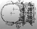
Essentially the same design as the original Virtuality 1000CS HMD (the one that looks like the monster from the movie Alien.)
Some non-so-clear teardown photos here: http://www.vrtifacts.com/hmds/all-brawn ... 000cs-hmd/
Some non-so-clear teardown photos here: http://www.vrtifacts.com/hmds/all-brawn ... 000cs-hmd/
-
zacherynuk
- Binocular Vision CONFIRMED!
- Posts: 296
- Joined: Sun Oct 03, 2010 2:56 pm
- Location: England
Re: Stereo HMD using mirrors
That's the one tone, I knew I had seen it somewhere - I really should have spent moretime searching your site!Tone wrote:Essentially the same design as the original Virtuality 1000CS HMD (the one that looks like the monster from the movie Alien.)
Some non-so-clear teardown photos here: http://www.vrtifacts.com/hmds/all-brawn ... 000cs-hmd/
-
Tone
- One Eyed Hopeful
- Posts: 42
- Joined: Fri Jun 25, 2010 9:13 am
- Location: USA
- Contact:
Re: Stereo HMD using mirrors
I should spend more time organizing my site. Stream of consciousness doesn't make for good reference material. Sorry about that!
-
zacherynuk
- Binocular Vision CONFIRMED!
- Posts: 296
- Joined: Sun Oct 03, 2010 2:56 pm
- Location: England
Re: Stereo HMD using mirrors
Here are some preliminary pictures:
http://www.wastedspace.co.uk/hmd/mirproj/" onclick="window.open(this.href);return false;
My maths and the IPD failed me after all and I need a more acute angle* to get the whole screen in - damned widescreen!
Prototype #1 involves me wearing swimming goggles with the optics in, this way I can play with blinkering, focus and the oh-so-important IPD/Image alignment - If only some 3D driver did overlap adjustment!
The unit is left open at the moment so that I can adjust and see the outside world etc.
Next step, really is cable extension, currently I am at too greater risk of breaking something.
*Or smaller mirror, screen a 1CM further away and more powerful optics (or less FOV) according to quick finger calculations.
-
3dvison
- Diamond Eyed Freakazoid!
- Posts: 718
- Joined: Sun Oct 24, 2010 7:25 pm
Re: Stereo HMD using mirrors
If you were to build your own HMD shell with out using a V6 or V8 shell as a starting point, could both LCD panels be placed off to the left and right sides of the head but far enough away so smaller 45deg mirrors could be used so they could be adjusted left and right for eye spacing ? Then each eyes image would need the same type of correction for a mirrored image only not two different types of correction for each eye ?zacherynuk wrote:It'll be a PITA, one screen will be inverted and reversed, one will be reversed!Okta wrote:What will be displayed in windows before you start a game with iz3d? One screen ok and the other reversed?
-
3dvison
- Diamond Eyed Freakazoid!
- Posts: 718
- Joined: Sun Oct 24, 2010 7:25 pm
Re: Stereo HMD using mirrors
I am sorry you posted pictures while I was typing.
I had it wrong.
For some reason I thought one LCD was going to be mounted on the side of one eye and the other above or below the other eye.
I had it all wrong.
So won't you just need mirror flip for both eyes ?
And if the LCD panels were moved farther to the sides with more distance between the lCD and the mirror could you then use smaller mirrors giving you more space for left and right eye spacing ?
-
zacherynuk
- Binocular Vision CONFIRMED!
- Posts: 296
- Joined: Sun Oct 03, 2010 2:56 pm
- Location: England
Re: Stereo HMD using mirrors
Indeed, I have smaller FS Mirrors here which I will try. Obviously smaller mirrors, means moving screen farther away and reducing imagine size, but allows you to bring the mirror in together to make image alignment much easier.3dvison wrote:If you were to build your own HMD shell with out using a V6 or V8 shell as a starting point, could both LCD panels be placed off to the left and right sides of the head but far enough away so smaller 45deg mirrors could be used so they could be adjusted left and right for eye spacing ? Then each eyes image would need the same type of correction for a mirrored image only not two different types of correction for each eye ?zacherynuk wrote:It'll be a PITA, one screen will be inverted and reversed, one will be reversed!Okta wrote:What will be displayed in windows before you start a game with iz3d? One screen ok and the other reversed?
Image alignment is taken for granted but it's really bloody hard.
Ensure your design allows for various movement, both swivel and slide.
Currently my screen are the same way up, so I couldn't actually use the 3D drivers now, but I can show a desktop in order to get my geometries correct.
-
zacherynuk
- Binocular Vision CONFIRMED!
- Posts: 296
- Joined: Sun Oct 03, 2010 2:56 pm
- Location: England
Re: Stereo HMD using mirrors
Aah, no the reason for those descriptions are because the IZ3D drivers only do a certain range of flipping - currently they won't do a simply horizontal flip of both outputs, but they do do a horizonal flip of one and a horizonal AND vertical flip of the other.... Knowing that should ease your confusion! lol3dvison wrote:I am sorry you posted pictures while I was typing.
I had it wrong.
For some reason I thought one LCD was going to be mounted on the side of one eye and the other above or below the other eye.
I had it all wrong.
So won't you just need mirror flip for both eyes ?
And if the LCD panels were moved farther to the sides with more distance between the lCD and the mirror could you then use smaller mirrors giving you more space for left and right eye spacing ?
-
3dvison
- Diamond Eyed Freakazoid!
- Posts: 718
- Joined: Sun Oct 24, 2010 7:25 pm
Re: Stereo HMD using mirrors
OK so in windows 7 you could do a simple horizontal flip of both displays and do regular desktop computing fine...? Is that correct ?zacherynuk wrote: Aah, no the reason for those descriptions are because the IZ3D drivers only do a certain range of flipping - currently they won't do a simply horizontal flip of both outputs, but they do do a horizonal flip of one and a horizonal AND vertical flip of the other...
-
zacherynuk
- Binocular Vision CONFIRMED!
- Posts: 296
- Joined: Sun Oct 03, 2010 2:56 pm
- Location: England
Re: Stereo HMD using mirrors
I wish. In my Windows 7 (Nvidia 295 gfx) it only flips the vertical access, not the horizontal.3dvison wrote:OK so in windows 7 you could do a simple horizontal flip of both displays and do regular desktop computing fine...? Is that correct ?zacherynuk wrote: Aah, no the reason for those descriptions are because the IZ3D drivers only do a certain range of flipping - currently they won't do a simply horizontal flip of both outputs, but they do do a horizonal flip of one and a horizonal AND vertical flip of the other...
-
3dvison
- Diamond Eyed Freakazoid!
- Posts: 718
- Joined: Sun Oct 24, 2010 7:25 pm
Re: Stereo HMD using mirrors
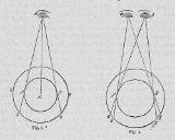
Would adding one more set of mirrors fix the horizon flip from the first set of mirrors ?
All slashes / \ are 45deg mirrors and all dotted lines --are LCD panels at zero deg. the (. .) is your head and eyes. Multiple Dots....are just to line up the diagram.
......... head
mirror/ (. .) \mirror
. LCD _ / \ _ LCD
...mirror. .mirror
The second set of mirrors are in front of your eyes , and they recieve the image of LCD panels from first set of mirrors.
The first set of mirrors and the LCD panels are more inline with one another and farther off to the side of the head than the diagram makes it look.
I NEED to READ and Remember..Ha Ha That would be a STEREOSCOPE.
You did not want a STEREOSCOPE....Sorry once again...
-
Fredz
- Petrif-Eyed
- Posts: 2255
- Joined: Sat Jan 09, 2010 2:06 pm
- Location: Perpignan, France
- Contact:
Re: Stereo HMD using mirrors
Hey, it's your site Tone ? It's been a great reference, thanks for that !
If you could correct the display problems with Google Chrome that would be nice, currently the texts in header are superposed to a copy of the banner image which makes it hardly readable. I had to get back to Internet Explorer to be able to read it comfortably.
If you could correct the display problems with Google Chrome that would be nice, currently the texts in header are superposed to a copy of the banner image which makes it hardly readable. I had to get back to Internet Explorer to be able to read it comfortably.
-
Tone
- One Eyed Hopeful
- Posts: 42
- Joined: Fri Jun 25, 2010 9:13 am
- Location: USA
- Contact:
Re: Stereo HMD using mirrors
Fredz - thanks for catching the Chrome problem. All better now. Would be sinful to force anyone to use IE.
As to the mirror design, my recommendations based on tinkering I've done over the years.
The center of each eye will be 33 mm to the right or left of the seam where the two mirrors touch (each half of your 66mm IPD.) You can actually mark the spot on each mirror, as it will be 46.68mm along the glass from the seam edge (that's 33mm / cos(45) = 33 / .707 = 46.68mm)
You can draw an imaginary line from that 46.68mm point on each mirror which is exactly perpendicular to your line of sight, out towards the LCDs. You're essentially ray tracing your IPD line of sight into the mirror and then along the ray that the mirror bounces.
Finally, you just slide the LCD in it's own plane (forward or backward alongside your head), until the imaginary line intersects the exact center of the display. Your IPD will be aligned perfectly for an image at an infinite distance, i.e. to fuse the two images, your eyes will not need to turn inward or outward.
Regarding enclosures, this design is perfect for a two piece thermoform shell. Use identical top and bottom pieces that grasp the mirrors and LCDs when the two shell halves are clamped together. Same approach as the MRG2.2. Thermoform is a great DIY process. You can do it roughly with your kitchen oven, a vacuum cleaner and a wooden frame with a pegboard top. I make replacement light blocks for the VR-4 this way (have to send the wife off on a diversionary errand beforehand!) Alternatively, you can find a local shop who'll do a one-off for you on a professional machine. The hard part is making up the mold.
You're definitely on the right track for wide field of view and high resolution. Given the size and weight, there's a considerable moment of inertia in this rig. Careful not to pull any muscles in your neck as you whirl around in the virtual world.
As to the mirror design, my recommendations based on tinkering I've done over the years.
- Move the mirrors as close as possible to your eyes. A cutout for the nose makes this possible.
- Mirrors should be exactly 45 deg.
- Displays should be exactly 90 deg.
- To adjust the IPD, slide the displays front to rear (in head-space), i.e. you'll wind up with some of the display approaching your temples.
The center of each eye will be 33 mm to the right or left of the seam where the two mirrors touch (each half of your 66mm IPD.) You can actually mark the spot on each mirror, as it will be 46.68mm along the glass from the seam edge (that's 33mm / cos(45) = 33 / .707 = 46.68mm)
You can draw an imaginary line from that 46.68mm point on each mirror which is exactly perpendicular to your line of sight, out towards the LCDs. You're essentially ray tracing your IPD line of sight into the mirror and then along the ray that the mirror bounces.
Finally, you just slide the LCD in it's own plane (forward or backward alongside your head), until the imaginary line intersects the exact center of the display. Your IPD will be aligned perfectly for an image at an infinite distance, i.e. to fuse the two images, your eyes will not need to turn inward or outward.
Regarding enclosures, this design is perfect for a two piece thermoform shell. Use identical top and bottom pieces that grasp the mirrors and LCDs when the two shell halves are clamped together. Same approach as the MRG2.2. Thermoform is a great DIY process. You can do it roughly with your kitchen oven, a vacuum cleaner and a wooden frame with a pegboard top. I make replacement light blocks for the VR-4 this way (have to send the wife off on a diversionary errand beforehand!) Alternatively, you can find a local shop who'll do a one-off for you on a professional machine. The hard part is making up the mold.
You're definitely on the right track for wide field of view and high resolution. Given the size and weight, there's a considerable moment of inertia in this rig. Careful not to pull any muscles in your neck as you whirl around in the virtual world.
-
Tone
- One Eyed Hopeful
- Posts: 42
- Joined: Fri Jun 25, 2010 9:13 am
- Location: USA
- Contact:
Re: Stereo HMD using mirrors
I just realized that I had the remnants of a mirror stereo viewer prototype based on 2.45" displays (480x234) from Unipack. The photos below show the what's left of this experiment. Got about 60 deg. FOV with a single lens. Whole thing is built up on a G-10 FR4 fiberglass frame (circuit board material http://en.wikipedia.org/wiki/FR-4), glued together with epoxy and spray painted matte black.
You do not have the required permissions to view the files attached to this post.
-
cybereality
- 3D Angel Eyes (Moderator)
- Posts: 11407
- Joined: Sat Apr 12, 2008 8:18 pm
Re: Stereo HMD using mirrors
Ah, the memories...Tone wrote:Essentially the same design as the original Virtuality 1000CS HMD (the one that looks like the monster from the movie Alien.)
Some non-so-clear teardown photos here: http://www.vrtifacts.com/hmds/all-brawn ... 000cs-hmd/
-
Fredz
- Petrif-Eyed
- Posts: 2255
- Joined: Sat Jan 09, 2010 2:06 pm
- Location: Perpignan, France
- Contact:
Re: Stereo HMD using mirrors
Thanks for the website correction Tone, that was fast ! 
-
zacherynuk
- Binocular Vision CONFIRMED!
- Posts: 296
- Joined: Sun Oct 03, 2010 2:56 pm
- Location: England
Re: Stereo HMD using mirrors
Tone wrote:Fredz - thanks for catching the Chrome problem. All better now. Would be sinful to force anyone to use IE.
As to the mirror design, my recommendations based on tinkering I've done over the years.
The IPD sweet spot can be easily determined. Let's assume your eyes are 66mm apart. Also assume the mirrors are at a 45 deg. angle to your line of sight (the two mirrors form a 90 deg. internal angle), and the mirrors come together and touch in the middle.
- Move the mirrors as close as possible to your eyes. A cutout for the nose makes this possible.
- Mirrors should be exactly 45 deg.
- Displays should be exactly 90 deg.
- To adjust the IPD, slide the displays front to rear (in head-space), i.e. you'll wind up with some of the display approaching your temples.
The center of each eye will be 33 mm to the right or left of the seam where the two mirrors touch (each half of your 66mm IPD.) You can actually mark the spot on each mirror, as it will be 46.68mm along the glass from the seam edge (that's 33mm / cos(45) = 33 / .707 = 46.68mm)
You can draw an imaginary line from that 46.68mm point on each mirror which is exactly perpendicular to your line of sight, out towards the LCDs. You're essentially ray tracing your IPD line of sight into the mirror and then along the ray that the mirror bounces.
Finally, you just slide the LCD in it's own plane (forward or backward alongside your head), until the imaginary line intersects the exact center of the display. Your IPD will be aligned perfectly for an image at an infinite distance, i.e. to fuse the two images, your eyes will not need to turn inward or outward.
Regarding enclosures, this design is perfect for a two piece thermoform shell. Use identical top and bottom pieces that grasp the mirrors and LCDs when the two shell halves are clamped together. Same approach as the MRG2.2. Thermoform is a great DIY process. You can do it roughly with your kitchen oven, a vacuum cleaner and a wooden frame with a pegboard top. I make replacement light blocks for the VR-4 this way (have to send the wife off on a diversionary errand beforehand!) Alternatively, you can find a local shop who'll do a one-off for you on a professional machine. The hard part is making up the mold.
You're definitely on the right track for wide field of view and high resolution. Given the size and weight, there's a considerable moment of inertia in this rig. Careful not to pull any muscles in your neck as you whirl around in the virtual world.
Been away for a few days, just had time to digest this - it makes very very good sense (as always!) - I love the IPD adjust with the LCD sliding - that's so bloody simple as to be magic - it importantly means that simple head mounts can be used, without complex IPD adjustments and the entire unit can be single peice.
Once I have the proof of concept going, using the acrylic sheeting, I'll look into the thermoforming - as that should be lighter (I think). I am also ordering some 1mm thick mirrors, which will dramatically cut down the weight of the rig.
I need to find the balance between biggest mirrors possible and also get some extension cables built...
zach
-
mAchiNE
- Binocular Vision CONFIRMED!
- Posts: 276
- Joined: Wed Sep 01, 2010 7:58 pm
Re: Stereo HMD using mirrors
Hey zacherynuk sounds like a promising project!
Any progress on this?
Any progress on this?
Current System:
Oculus Rift Dev Kit, 3x 23" Passive 3D Monitors in 3D Vision Surround, Novint Falcon, 3rd Space Gaming Vest, ButtKicker, Razer Hydra, Logitech G25.
Previous 3D Systems:
Viewsonic PJD6531w 3D DLP Projector, Vuzix VR920, 24" Alienware and 22" Samsung 3D Vision Monitors, eDimensional 3D Glasses with 19" CRT Monitor
-
zacherynuk
- Binocular Vision CONFIRMED!
- Posts: 296
- Joined: Sun Oct 03, 2010 2:56 pm
- Location: England
Re: Stereo HMD using mirrors
Not a great deal, there is an update here: http://www.wastedspace.co.uk/cms/2011/0 ... t-part-13/mAchiNE wrote:Hey zacherynuk sounds like a promising project!
Any progress on this?
The idea is still sound and have had fun testing - however i need to get those LVDS cables extended!
Been a little sidetracked with nice weather, and a new toy: http://www.youtube.com/watch?v=CDpolBRDKcQ
zach
-
cadcoke5

- Binocular Vision CONFIRMED!
- Posts: 210
- Joined: Mon May 24, 2010 8:43 pm
- Location: near Lancaster, PA USA
Re: Stereo HMD using mirrors
I see that in your HMD setup, the user can see the display both through the mirror and directly. Those privacy screens sold for laptop computers may be a solution for that if it is an issue.
By the way, I did ask a guy with a construction helmet about his preferred straps, and he said that he strongly recommended the kind that has a "Nape strap" with a ratchet knob. A nape strap goes around thw lower part of the back of your head. He said you can hang upside down with one of these and your hat won't come off.
Joe Dunfee
-
mAchiNE
- Binocular Vision CONFIRMED!
- Posts: 276
- Joined: Wed Sep 01, 2010 7:58 pm
Re: Stereo HMD using mirrors
That RC Drone with the headtracked camera looks like a lot of fun! did you do that mod yourself?
I had a look at your post on your blog, extending those cables shouldn't be too hard if you know how to solder but I'm not sure how long you can make that sort of thing before the signal loss starts to affect image quality, maybe someone else here will know.
if you don't want to butcher the signal part of the cabe (the long black 30 pin plug) too much you could try make up an extension, it looks like its just a standard 30 pin header, you should be able to get a male and female plug the same as that from an electronics store and make an extension with some CAT5 cable, this should allow you to experiment with cable lengths. If you can find matching plugs and sockets for the power wires (red and white wires) you can extend them as well or just cut the wire and extend it. I would offer to help you with this but I am in New Zealand.
Also how heavy is the HMD so far? and did you figure out how you are going to allow the movement of the LCD panels for IPD adjustment yet? (I assume both panels will have to move together to keep the image centred)
Current System:
Oculus Rift Dev Kit, 3x 23" Passive 3D Monitors in 3D Vision Surround, Novint Falcon, 3rd Space Gaming Vest, ButtKicker, Razer Hydra, Logitech G25.
Previous 3D Systems:
Viewsonic PJD6531w 3D DLP Projector, Vuzix VR920, 24" Alienware and 22" Samsung 3D Vision Monitors, eDimensional 3D Glasses with 19" CRT Monitor
Oculus Rift Dev Kit, 3x 23" Passive 3D Monitors in 3D Vision Surround, Novint Falcon, 3rd Space Gaming Vest, ButtKicker, Razer Hydra, Logitech G25.
Previous 3D Systems:
Viewsonic PJD6531w 3D DLP Projector, Vuzix VR920, 24" Alienware and 22" Samsung 3D Vision Monitors, eDimensional 3D Glasses with 19" CRT Monitor
-
PalmerTech
- Golden Eyed Wiseman! (or woman!)
- Posts: 1644
- Joined: Fri Aug 21, 2009 9:06 pm
Re: Stereo HMD using mirrors
I have the same LCD you have, several, actually. I bought 3 extra LVDS cables from Vitrolight, to experiment with extending.
Other LVDS cables I have extended in the past (laptop screens, used for DIY projectors) have been very finicky in how long you can extend them. I am going to see if I can extend it a bit using the most overkill technique I know, which is using ground+signal twisted pairs with ferrite filters on both ends. If I can get that to work, then I will see if I can get away with more simple ways. If I am successful, I would be glad to sell you some extension cables for a few dollars to cover the parts!
Other LVDS cables I have extended in the past (laptop screens, used for DIY projectors) have been very finicky in how long you can extend them. I am going to see if I can extend it a bit using the most overkill technique I know, which is using ground+signal twisted pairs with ferrite filters on both ends. If I can get that to work, then I will see if I can get away with more simple ways. If I am successful, I would be glad to sell you some extension cables for a few dollars to cover the parts!
-
zacherynuk
- Binocular Vision CONFIRMED!
- Posts: 296
- Joined: Sun Oct 03, 2010 2:56 pm
- Location: England
Re: Stereo HMD using mirrors
Hi,
Thanks for all the feedback, folks!
Those pesky wires are just too small for me to solder, and I didn’t have any luck tracking down the correct board/cable terminators nor do I have crimps that small… I tried kroning into RJ45 to no avail also. Bloody tiny they are. And they melt. Drivin’ me nuts.
Good idea re privacy screen, hoping not to have to add anymore weight though – we’ll see once I finish the adjustable design. I am hoping end of august (family leaving me alone for a day or two!) for a nice working head unit.
The Quad is an Xaircraft X450, I made the cam mount. Servo mechanism is standard. Video is via 2.4Ghz FatShark – not superb, but very good fun. First two people to stand next to me with the visor on, whilst I flew around fell over within seconds! So it’s a sit down to use policy now
-
mAchiNE
- Binocular Vision CONFIRMED!
- Posts: 276
- Joined: Wed Sep 01, 2010 7:58 pm
Re: Stereo HMD using mirrors
Because driver the boards for your LCD screens have HDMI inputs you might find this useful:
http://www.cypconverters.com.au/other-p ... h-322.html" onclick="window.open(this.href);return false;
Its a 3D Demultiplexer which takes a HDMI 1.4 signal and splits it into the left and right frames and outputs them from 2 HDMI ports in regular HDMI format.
With this device you can plug your DIY HMD into a 3D Bluray player or a Playstation 3 and watch/play in 3D!
I read on a AV forum that they cost $295USD and come with a HDMI 1.4 splitter (required) for $100USD so total cost is $395USD plus shipping. (on the AV forum someone said it was about $500USD total inc shipping - it ships from Australia)
Its a bit pricey but adding HDMI 1.4 support to a DIY HMD could be worth it! (or at least we know these devices exist and maybe they will get cheaper)
Current System:
Oculus Rift Dev Kit, 3x 23" Passive 3D Monitors in 3D Vision Surround, Novint Falcon, 3rd Space Gaming Vest, ButtKicker, Razer Hydra, Logitech G25.
Previous 3D Systems:
Viewsonic PJD6531w 3D DLP Projector, Vuzix VR920, 24" Alienware and 22" Samsung 3D Vision Monitors, eDimensional 3D Glasses with 19" CRT Monitor
Oculus Rift Dev Kit, 3x 23" Passive 3D Monitors in 3D Vision Surround, Novint Falcon, 3rd Space Gaming Vest, ButtKicker, Razer Hydra, Logitech G25.
Previous 3D Systems:
Viewsonic PJD6531w 3D DLP Projector, Vuzix VR920, 24" Alienware and 22" Samsung 3D Vision Monitors, eDimensional 3D Glasses with 19" CRT Monitor
-
jjzurro
- One Eyed Hopeful
- Posts: 1
- Joined: Thu Jul 28, 2011 6:43 am
Re: Stereo HMD using mirrors
Hi everyone. I'm new in the forum and I'm from Spain, so be gentle with my english.
I really like your idea and I have some questions.
Can we use a similar configuration to see this 2 screens like only one in front of us (using mirrors)? This way we'll have a screen with 2560x720 and this will be resolve the problem of the FOV. And when the time is right (I hope soon)...
Have you seen this?
http://www.engadget.com/2011/07/20/hita ... artphones/
We can have 2 3d HD screen (2560x720) and make a super high involving HMD. (I suppose we'll have to sell a kidney to buy a computer with this power but.... I wanna see it soon !!!!
I think it can be also interesting ...
Regards.
-
PalmerTech
- Golden Eyed Wiseman! (or woman!)
- Posts: 1644
- Joined: Fri Aug 21, 2009 9:06 pm
Re: Stereo HMD using mirrors
@jjzurro: The problem with that technique is that the center of the screens is too far out, and we currently have no good ways to shift the image as much as we need to, via hardware or software.
@zach: I figured out how to extend the LVDS connection! A real bugger, it was. In the end, I managed to make an extension about 3.5 feet long. It uses twisted pairs taken from RJ45 cables, and I also had to shield it very, very well with several layers of 3M gold/silver shielding tape. Without it, the image would not even go through, and with just a single layer, the image showed up with some serious artifacts. After another solid layer and some extra around the very ends, it works perfectly! I can take some pictures, if you like.
If the wires are too small for you to solder, you might want to consider soldering to some pin headers, and pressing them into the connector of the original cable. Solder to those, and then just wire the other end directly to the driver board (I did that part myself).
@zach: I figured out how to extend the LVDS connection! A real bugger, it was. In the end, I managed to make an extension about 3.5 feet long. It uses twisted pairs taken from RJ45 cables, and I also had to shield it very, very well with several layers of 3M gold/silver shielding tape. Without it, the image would not even go through, and with just a single layer, the image showed up with some serious artifacts. After another solid layer and some extra around the very ends, it works perfectly!
If the wires are too small for you to solder, you might want to consider soldering to some pin headers, and pressing them into the connector of the original cable. Solder to those, and then just wire the other end directly to the driver board (I did that part myself).
-
cadcoke5
- Binocular Vision CONFIRMED!
- Posts: 210
- Joined: Mon May 24, 2010 8:43 pm
- Location: near Lancaster, PA USA
Re: Stereo HMD using mirrors
I just saw a video about a telepresence robot, but what what caught my eye was the HMD the user was wearing. I have no information other than what was posted at Diginfo. From the video, I see it obviously has mirrors or prisms in front of the user's eyes, and those reflect to displays that are approximately 4" or 5" size. Since it is a university project, perhaps there is more information available at the university, or perhaps by tracking down some of the people involved.
"TELESAR V is a telexistence robot system, being researched by a group at Keio University led by Professor Tachi."
"The operator uses a 3D head mounted display which covers the entire field of view."
The diginfo article; http://www.diginfo.tv/2011/11/07/11-0225-r-en.php" onclick="window.open(this.href);return false;
Direct link to the video; http://www.youtube.com/watch?v=ZMF0p15G ... r_embedded" onclick="window.open(this.href);return false;
Joe Dunfee
-
OzOnE2k10
- Sharp Eyed Eagle!
- Posts: 436
- Joined: Wed Jan 13, 2010 7:12 am
- Location: UK
Re: Stereo HMD using mirrors
@Tone: Thanks for the web site first of all! Many years of info, and some amazing retro stuff on there.
(That damned woman at Disney told us we should go on The Carousel of Progress, "It's gonna be a fantastic ride". lol)
Hi, Zach,
(WARNING: InfoBomb incoming!)...
I'm very interested in this. It looks like a simple enough way of getting a wider FOV with decent resolution.
Like most of us, I've been looking for a decent (but relatively cheap) VR setup for the best part of twenty years now.
Ever since I saw Lawnmower Man in '92 I've wanted to experience a wide FOV setup with 3D and head tracking.
(btw, I just watched the movie again yesterday for the first time in five years. Not the best film ever, but inspiring. lol)
Did you manage to extend the LVDS cables yet? If not, I might be able to help somewhat...
Firstly, could you confirm that there are only the 12 (or so) wires connecting to the main board on the black connector? It looks like there is only one row of wires at the LCD plug end, so this would be 25 wires?
It looks like the extra unused wires at the mainboard end are tucked away inside the black heatshrink? It's probably not necessary to confirm this, but does this look correct to you?
According to your FleaBay link, it gives the LCD model. The link to the datasheet seems broken, but Google has it (do your LCD's have the model number on them?)...
http://www.azdisplays.com/PDF/HV056WX1-100.pdf
On page 12 it shows the pinouts. You should be able to use a multimeter to work out the cable connections and pinouts for the mainboard end.
There are only a few wires used, so it shouldn't be too bad. Once you have the pinouts, you can check if they appear to match datasheet too.
What do the labels say on the White and Red wires ("GND" / "5V")?
This looks like this is the main power to the LCD, or the backlight? Looks like it has an LED backlight?
As you probably know, the LVDS signals run at a high speed, so longer cables could cause problems. A good idea might be to use an HDMI cable instead. A decent HDMI cable is designed for MUCH higher speeds than this. HDMI also has the correct number of twisted-pair wires, plus a few extra pins for your other few LCD control signals.
Soldering the mainboard connector won't be so bad (almost certainly 2mm pin pitch, judging by your close-up pics)....
http://www.wastedspace.co.uk/hmd/tmp/lvds/
The LCD connector might be a pain though.
It depends if you're willing to risk a cable, or try to find a similar cable from an LCD TV or laptop?
You should be able to buy the LCD connector from d1giK3Y (I think it might be a JAE FI-R type?), but I personally think it would be far easier to cut the existing cable and solder the wires to an HDMI socket.
An easier way to solder to the HDMI sockets would be to buy a cheap HDMI switch box. They very often breakout the pins to some "cheap and nasty" (low speed) switches. You can remove the switches and solder the LCD cable wires to the PCB instead. This will give you another couple of spare HDMI sockets for the other LCD panel.
Obviously you'll need an HDMI socket at the LCD end, so you might have to cut down the switch box PCB to save space / weight?
Some people on the Interweb have had success with manually wiring LVDS cables with invidual Kynar wires, but that will probably look bad and may not work for longer cables.
It might even work to just cut the existing LCD cable, then cut the plugs off an HDMI cable and join the wires. Make sure you have the pinouts first though!
I can help with building the cable if you like? I'm in Devon btw, I have a fair bit of electronics experience and Metcal solder / hot air / desoldering stations etc.
I'm sure this can be done quite easily. I'd love to see this HMD in action.
Cheers,
OzOnE.
P.S. I recently signed up on Alib*b* to buy an HDMI 3D converter. As expected, it doesn't do what the specs say, only 2D-3D conversion for SBS-H / Anaglyph.
Anywho, they have some nice 0.6" and 0.97" true SVGA OLED modules in single quantities from China. I haven't asked for prices yet, but you never know, they might be cheap.