Thats rather awesome. Remembering stuff like manually polishing telescope lenses was what made me wonder if we couldn't just 3D print the basic shape of these lenses in future, then put them through a final 'polish' like that, to achieve lenses of the correct shape in a much quicker time than making them from scratch from blanks...
Looking forward to seeing how the mirrors turn out!
Compact 180 deg fov HMD's still possible?
-
WiredEarp
- Golden Eyed Wiseman! (or woman!)
- Posts: 1498
- Joined: Fri Jul 08, 2011 11:47 pm
-
PalmerTech
- Golden Eyed Wiseman! (or woman!)
- Posts: 1644
- Joined: Fri Aug 21, 2009 9:06 pm
Re: Compact 180 deg fov HMD's still possible?
Nah, making them from blanks will almost certainly be easier. 3D printing is actually really, really slow, especially for finer objects.
-
FingerFlinger
- Sharp Eyed Eagle!
- Posts: 429
- Joined: Tue Feb 21, 2012 11:57 pm
- Location: Irvine, CA
Re: Compact 180 deg fov HMD's still possible?
Probably a stupid idea, but what about cutting the basic lens shape from a 3D CNC mill and polishing it down that way?
I imagine casting them is still WAY easier, but using a CNC, you make design modifications quickly and without needing to fabricate new molds.
I imagine casting them is still WAY easier, but using a CNC, you make design modifications quickly and without needing to fabricate new molds.
-
ERP
- Cross Eyed!
- Posts: 101
- Joined: Sat Jul 31, 2010 12:08 pm
Re: Compact 180 deg fov HMD's still possible?
The issue with 3 axis mills is you always end up with the tool profile in the final piece, the usual way you get "smooth" shapes on a 3 Axis mill is to rough it out then use a small ball nosed cutter with a very small over lap to produce the final profile. That would not be accurate enough for the outside of a lens.FingerFlinger wrote:Probably a stupid idea, but what about cutting the basic lens shape from a 3D CNC mill and polishing it down that way?
I imagine casting them is still WAY easier, but using a CNC, you make design modifications quickly and without needing to fabricate new molds.
I guess you could likely do a final polish, to get the effect but I have to wonder if the mill would actually save you any time.
You probably be better off using some sort of single point cutter to rough the shape i.e. a lathe, but again your still going to need the final polish pass.
-
FingerFlinger
- Sharp Eyed Eagle!
- Posts: 429
- Joined: Tue Feb 21, 2012 11:57 pm
- Location: Irvine, CA
Re: Compact 180 deg fov HMD's still possible?
Yeah, that's a good point. A lathe isn't a bad idea, though. How are prototype lenses typically fabricated?
-
3dpmaster
- Cross Eyed!
- Posts: 116
- Joined: Tue Sep 21, 2010 3:05 pm
Re: Compact 180 deg fov HMD's still possible?
Thanks for your comments,
Cnc is ideal but in 2003 when I was a teenager, there was no money for cnc and no 3D printer.
I could only use some hobby materials and my brains.
Material list
the casting resin for lenses: 12 euro
diy spinning lens holder (fibreboard): 15 euro
diy vacuum forming pump and ring hole (1mm aluminum): 15 euro
polishing and sandpaper (p40 to p1000): 25 euro
silicone mold (standard bathroom silicone) : 5 euro
+ drill from my parents.
Fabrication of the resin casted lens (March 2003):
1. The lens material index is calculated, then the curvature of the lens surface is drawn on paper (diameter is very important).
2. Vacuumforming by blowing surface into a hemisphere with custom diameter ring hole.
2 (note) The diameter of the lens itsself and the diameter of the vacuum formed hemisphere are custom.
How smaller the hemisphere, how stronger the lens.
3. make a cylindrical shape and glue it WITHOUT GAPS on the inner side (for convex) or outher side(for concave) of the hemisphere.
4. Take the glued hemisphere and cylinder apart from the rest of the hemisphere around the cylinder by cutting (with siccors).
5. Put it into a mold like a ship (not over the open surface of the cylinder). you can put weights for maintain it right.
6. If the mold is dry, you can remove the 'ship'.
7. Poor the casting resin.
8. Let it dry.
9. remove it from the mold and grind the upper surface.
10. Fix it on a drillshaft (in the center) and let it spin.
11. Grind it with a sandpaper fixed on a metal shape with the same curvature as the lens.
12 polish in the same way.
13 remove from shaft and grind/polish the flat surface on a horizontal grinding/polishing disc.
I'll send an illustration because it is complicated that way .
Full immersive research:
HMD:
SONY HMZ-T1
FOV: 40° diagonal
HMD project:
FOV: >180°
Link: http://www.mtbs3d.com/phpBB/viewtopic.php?f=26&t=14332
HMD:
SONY HMZ-T1
FOV: 40° diagonal
HMD project:
FOV: >180°
Link: http://www.mtbs3d.com/phpBB/viewtopic.php?f=26&t=14332
-
3dpmaster
- Cross Eyed!
- Posts: 116
- Joined: Tue Sep 21, 2010 3:05 pm
Re: Compact 180 deg fov HMD's still possible?
The Focal length is the most difficult partPalmerTech wrote:The curve greatly magnifies the image, that is why it does not need traditional lenses. A projection surface only works with a collimated light source, such as a projection, and then you still need something to modify the focal length.
Full immersive research:
HMD:
SONY HMZ-T1
FOV: 40° diagonal
HMD project:
FOV: >180°
Link: http://www.mtbs3d.com/phpBB/viewtopic.php?f=26&t=14332
HMD:
SONY HMZ-T1
FOV: 40° diagonal
HMD project:
FOV: >180°
Link: http://www.mtbs3d.com/phpBB/viewtopic.php?f=26&t=14332
-
PalmerTech
- Golden Eyed Wiseman! (or woman!)
- Posts: 1644
- Joined: Fri Aug 21, 2009 9:06 pm
Re: Compact 180 deg fov HMD's still possible?
Yes, I know. I was responding to Okta's idea of projecting the microdisplay's image onto a flat white curved surface instead of a mirror, and that it would not work unless you added another lens anyway.3dpmaster wrote:The Focal length is the most difficult partPalmerTech wrote:The curve greatly magnifies the image, that is why it does not need traditional lenses. A projection surface only works with a collimated light source, such as a projection, and then you still need something to modify the focal length.
-
cadcoke5

- Binocular Vision CONFIRMED!
- Posts: 210
- Joined: Mon May 24, 2010 8:43 pm
- Location: near Lancaster, PA USA
Re: Compact 180 deg fov HMD's still possible?
I have previously mentioned the idea of using the flexible OLED displays for a Head Mounted Display. This would hopefully solve the issue of light on one portion of a projected image from somewhat washing out other portions of the screen. However, this technology has not been coming as fast as hoped. The writer in the article below says Samsung's late 2012 launch has been put off to perhaps early 2013. And even then, the mass market being perhaps delayed to 2014 or later.
Of course we have CES 2013 coming up in Jan. Perhaps there will be some surprises.
http://www.oled-info.com/thoughts-about ... -plausible
Joe Dunfee
Of course we have CES 2013 coming up in Jan. Perhaps there will be some surprises.
http://www.oled-info.com/thoughts-about ... -plausible
Joe Dunfee
-
Okta

- Golden Eyed Wiseman! (or woman!)
- Posts: 1515
- Joined: Tue Feb 12, 2008 5:22 am
Re: Compact 180 deg fov HMD's still possible?
I just checked the pictures againPalmerTech wrote:Yes, I know. I was responding to Okta's idea of projecting the microdisplay's image onto a flat white curved surface instead of a mirror, and that it would not work unless you added another lens anyway.3dpmaster wrote:The Focal length is the most difficult partPalmerTech wrote:The curve greatly magnifies the image, that is why it does not need traditional lenses. A projection surface only works with a collimated light source, such as a projection, and then you still need something to modify the focal length.
3dpmaster: when you say focal length is the biggest problem, do you mean the interfaces on areas of all the reflectors matching up or over all?
"I did not chip in ten grand to seed a first investment round to build value for a Facebook acquisition."
Notch on the FaceDisgrace buyout.
Notch on the FaceDisgrace buyout.
-
3dpmaster
- Cross Eyed!
- Posts: 116
- Joined: Tue Sep 21, 2010 3:05 pm
Re: Compact 180 deg fov HMD's still possible?
The Issue is the focal plane. Some beams from the observer's eye (set to infinity) have a larger focal length than other beams also set to infinity. With the mirror technique, most of the rays are inverted to +/- infinity before they reach the collimated lens.
The idea to set two micro projectors on the top of the head to project the image to a curved screen is not bad. If we use a pair of reading eye glasses, we can bring the curved screen closer to the observer's eye. The best screen to use, is a toroidal white curved projection screen. I have to try this technique, I hope It will works also.

The idea to set two micro projectors on the top of the head to project the image to a curved screen is not bad. If we use a pair of reading eye glasses, we can bring the curved screen closer to the observer's eye. The best screen to use, is a toroidal white curved projection screen. I have to try this technique, I hope It will works also.
Last edited by 3dpmaster on Fri Jun 28, 2013 9:22 am, edited 1 time in total.
Full immersive research:
HMD:
SONY HMZ-T1
FOV: 40° diagonal
HMD project:
FOV: >180°
Link: http://www.mtbs3d.com/phpBB/viewtopic.php?f=26&t=14332
HMD:
SONY HMZ-T1
FOV: 40° diagonal
HMD project:
FOV: >180°
Link: http://www.mtbs3d.com/phpBB/viewtopic.php?f=26&t=14332
-
3dpmaster
- Cross Eyed!
- Posts: 116
- Joined: Tue Sep 21, 2010 3:05 pm
Re: Compact 180 deg fov HMD's still possible?
Correction, the focal POINTS are not on a planar surface. Image below.
You do not have the required permissions to view the files attached to this post.
Full immersive research:
HMD:
SONY HMZ-T1
FOV: 40° diagonal
HMD project:
FOV: >180°
Link: http://www.mtbs3d.com/phpBB/viewtopic.php?f=26&t=14332
HMD:
SONY HMZ-T1
FOV: 40° diagonal
HMD project:
FOV: >180°
Link: http://www.mtbs3d.com/phpBB/viewtopic.php?f=26&t=14332
-
Hannibalj2
- Binocular Vision CONFIRMED!
- Posts: 300
- Joined: Sun May 26, 2013 2:45 pm
Re: Compact 180 deg fov HMD's still possible?
Any updates on your HMD?! Still very interesting! !!!!:)
Portal Dual 180+ HFOV HMD: http://www.mtbs3d.com/phpBB/viewtopic.php?f=26&t=18335
PORTAL DUAL VR, Downloads: http://hannibalj2.jimdo.com/
PORTAL DUAL VR, Downloads: http://hannibalj2.jimdo.com/
-
3dpmaster
- Cross Eyed!
- Posts: 116
- Joined: Tue Sep 21, 2010 3:05 pm
Re: Compact 180 deg fov HMD's still possible?
The mirrors are almost finished. It is hard to get proper mirrors. Any surface error on a curved mirror deforms the image badly.
I'll try to assembly between now and 15 days. Hopely it will work.
I'll try to assembly between now and 15 days. Hopely it will work.
Full immersive research:
HMD:
SONY HMZ-T1
FOV: 40° diagonal
HMD project:
FOV: >180°
Link: http://www.mtbs3d.com/phpBB/viewtopic.php?f=26&t=14332
HMD:
SONY HMZ-T1
FOV: 40° diagonal
HMD project:
FOV: >180°
Link: http://www.mtbs3d.com/phpBB/viewtopic.php?f=26&t=14332
-
Hannibalj2
- Binocular Vision CONFIRMED!
- Posts: 300
- Joined: Sun May 26, 2013 2:45 pm
Re: Compact 180 deg fov HMD's still possible?
Cool Mate, this project has been one of my fav's for a while!! 
Portal Dual 180+ HFOV HMD: http://www.mtbs3d.com/phpBB/viewtopic.php?f=26&t=18335
PORTAL DUAL VR, Downloads: http://hannibalj2.jimdo.com/
PORTAL DUAL VR, Downloads: http://hannibalj2.jimdo.com/
-
3dpmaster
- Cross Eyed!
- Posts: 116
- Joined: Tue Sep 21, 2010 3:05 pm
Re: Compact 180 deg fov HMD's still possible?
Sorry for the slow-step updates.
I don't know if this project is still DIY-valable. Even the most specialized CNC milling factory hesitates to build my mirrors.
Hopely I can fix the optical device in July.
Final work to do:
-focal measurements
-cnc and lathe carving the mirrors
-cnc and carving the lenses (pmma)
-optical assembly and optical alignment
-Connecting the modified HMZ-T1 to the optics
-Final test with predistorted images or video's
-Correct vignette distortion with other relay optics.
If everything works well, I could get a head mounted display with 3times the field of view of the Oculus Rift (I mean 270deg horizontally).
Only the vertical fov has to be full fov but first the horizontal way.
Full immersive research:
HMD:
SONY HMZ-T1
FOV: 40° diagonal
HMD project:
FOV: >180°
Link: http://www.mtbs3d.com/phpBB/viewtopic.php?f=26&t=14332
HMD:
SONY HMZ-T1
FOV: 40° diagonal
HMD project:
FOV: >180°
Link: http://www.mtbs3d.com/phpBB/viewtopic.php?f=26&t=14332
-
Hannibalj2
- Binocular Vision CONFIRMED!
- Posts: 300
- Joined: Sun May 26, 2013 2:45 pm
Re: Compact 180 deg fov HMD's still possible?
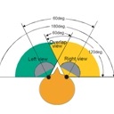
Over 200 horiz.deg!!!!!??? 
How do you think this compares to Antons InfinteEye?
I have been looking at that approach as well.
This all sound pretty exciting. Hows is the weight? What software are you using for the partial overlap? IZ3d?
Keep up the good work!
How do you think this compares to Antons InfinteEye?
I have been looking at that approach as well.
This all sound pretty exciting. Hows is the weight? What software are you using for the partial overlap? IZ3d?
Keep up the good work!
Portal Dual 180+ HFOV HMD: http://www.mtbs3d.com/phpBB/viewtopic.php?f=26&t=18335
PORTAL DUAL VR, Downloads: http://hannibalj2.jimdo.com/
PORTAL DUAL VR, Downloads: http://hannibalj2.jimdo.com/
-
3dpmaster
- Cross Eyed!
- Posts: 116
- Joined: Tue Sep 21, 2010 3:05 pm
Re: Compact 180 deg fov HMD's still possible?
Dear Hannibalj2
I think the weight would be the same as Oculus Rift.
InfiniteEye is different from the HMD I'm building: the screens of InfiniteEye are flat, not curved.
I didn't find any Software yet but I will start with distortion stills and distortion video's .... everything manual.
The overlap would be 80 deg. I hope to get 90 deg overlap if the optics are not too large.
I think the InfiniteEye has 180deg or 200deg fov, I don't know.
Full immersive research:
HMD:
SONY HMZ-T1
FOV: 40° diagonal
HMD project:
FOV: >180°
Link: http://www.mtbs3d.com/phpBB/viewtopic.php?f=26&t=14332
HMD:
SONY HMZ-T1
FOV: 40° diagonal
HMD project:
FOV: >180°
Link: http://www.mtbs3d.com/phpBB/viewtopic.php?f=26&t=14332
-
Hannibalj2
- Binocular Vision CONFIRMED!
- Posts: 300
- Joined: Sun May 26, 2013 2:45 pm
Re: Compact 180 deg fov HMD's still possible?
Hey, how is the unit coming along so far? I am building a 160-180 degree prototype. The light cardboard version I have may provide slightly larger FOV view than the newest one 3d printed one. But the newer model would fit more snugly and comfy.
How are you lenses coming along?
Cheers man!
How are you lenses coming along?
Cheers man!
Portal Dual 180+ HFOV HMD: http://www.mtbs3d.com/phpBB/viewtopic.php?f=26&t=18335
PORTAL DUAL VR, Downloads: http://hannibalj2.jimdo.com/
PORTAL DUAL VR, Downloads: http://hannibalj2.jimdo.com/
-
3dpmaster
- Cross Eyed!
- Posts: 116
- Joined: Tue Sep 21, 2010 3:05 pm
Re: Compact 180 deg fov HMD's still possible?
Dear Hannibalj2
The lenses are not ready yet, a lot of errors in the construction have delayed my schedule for weeks.
I took contact with several optical companies to construct a custom lens but it costs thousands of dollars.
The diamond milled metallic mold is extremely precise but this rises up the prise.
So after a lot of trials and errors I can get my proper lenses (hopefully in September).
Full immersive research:
HMD:
SONY HMZ-T1
FOV: 40° diagonal
HMD project:
FOV: >180°
Link: http://www.mtbs3d.com/phpBB/viewtopic.php?f=26&t=14332
HMD:
SONY HMZ-T1
FOV: 40° diagonal
HMD project:
FOV: >180°
Link: http://www.mtbs3d.com/phpBB/viewtopic.php?f=26&t=14332
-
MyCrtFellOnMe
- One Eyed Hopeful
- Posts: 3
- Joined: Sun Sep 22, 2013 9:31 am
Re: Compact 180 deg fov HMD's still possible?
Really cool stuff! Hope you were able to get those lenses!
-
Easter6
- One Eyed Hopeful
- Posts: 15
- Joined: Wed Apr 30, 2014 5:21 pm
Re: Compact 180 deg fov HMD's still possible?
apologies for being so late to this party, lol I only found this forum today...
I see there's some peeps trying to do some funky stuff with mirrors, and it seems mirrors can be tricky. I just wanted to put my two cents in.. maybe it will be informative, or just noise, lol
I remember quite a while back an interview was done with a mathematician who liked to turn math into mirrors, so to speak. for some reason I like to remember this interview as appearing in a printed issue of Wired but all I can dig up now are blurbs from other sources. If anyone can shed some light on producing the kind of mirrors that would give a sweet FOV, he could be the guy.
Here's some links I found:
http://www.newscientist.com/gallery/dn1 ... ng-mirrors
(image #1, 2 and 3 in particular are pretty cool!)
also, his 'personal' page seems to be here:
http://www.math.drexel.edu/~ahicks/
not sure if any of this can be of any help, but hey, it can't possibly hurt!
-
3dpmaster
- Cross Eyed!
- Posts: 116
- Joined: Tue Sep 21, 2010 3:05 pm
Re: Compact 180 deg fov HMD's still possible?
I will make a link on my havatar
Full immersive research:
HMD:
SONY HMZ-T1
FOV: 40° diagonal
HMD project:
FOV: >180°
Link: http://www.mtbs3d.com/phpBB/viewtopic.php?f=26&t=14332
HMD:
SONY HMZ-T1
FOV: 40° diagonal
HMD project:
FOV: >180°
Link: http://www.mtbs3d.com/phpBB/viewtopic.php?f=26&t=14332
-
3dpmaster
- Cross Eyed!
- Posts: 116
- Joined: Tue Sep 21, 2010 3:05 pm
Re: Compact 180 deg fov HMD's still possible?
I stumbled upon this website two years ago, thank you for sharing this. I learned a lot about the way how aspherized panoramic omnidirectional mirrors work.Easter6 wrote:apologies for being so late to this party, lol I only found this forum today...
I see there's some peeps trying to do some funky stuff with mirrors, and it seems mirrors can be tricky. I just wanted to put my two cents in.. maybe it will be informative, or just noise, lol
I remember quite a while back an interview was done with a mathematician who liked to turn math into mirrors, so to speak. for some reason I like to remember this interview as appearing in a printed issue of Wired but all I can dig up now are blurbs from other sources. If anyone can shed some light on producing the kind of mirrors that would give a sweet FOV, he could be the guy.
Here's some links I found:
http://www.newscientist.com/gallery/dn1 ... ng-mirrors
(image #1, 2 and 3 in particular are pretty cool!)
also, his 'personal' page seems to be here:
http://www.math.drexel.edu/~ahicks/
not sure if any of this can be of any help, but hey, it can't possibly hurt!
He could make those magnificiant mirrors by combining the hollow sides and a hyperboloid top, I think.
Each of his mirrors has a specific focal point that is used to determine reflections in aspherical mode. But still, very interesting.
It is a wile, I know that you and other guys from Mtbs are waiting for the progress of my amazing 180+fov project.
The project did not fail, but is still on the road. I want to finish it, but with the artistic projects I have, the 180+fov project is still on queue. I also have to make new mirrors, a new mounting frame and I have to find microdisplays.
This is the biggest problem: where to get hi-res microdisplays?
Sinds the use of curved mirrors, there is no need for Oculus-like 7inch screens. A microdisplay of 0.7 inch also works well.
I tried the microdisplays from Sony HMZ-T1 but these are too dark
The link about my mirrors I'm talking about is : http://www.mtbs3d.com/phpBB/viewtopic.php?f=26&t=14857
Full immersive research:
HMD:
SONY HMZ-T1
FOV: 40° diagonal
HMD project:
FOV: >180°
Link: http://www.mtbs3d.com/phpBB/viewtopic.php?f=26&t=14332
HMD:
SONY HMZ-T1
FOV: 40° diagonal
HMD project:
FOV: >180°
Link: http://www.mtbs3d.com/phpBB/viewtopic.php?f=26&t=14332
-
Easter6
- One Eyed Hopeful
- Posts: 15
- Joined: Wed Apr 30, 2014 5:21 pm
Re: Compact 180 deg fov HMD's still possible?
3dpmaster wrote: I stumbled upon this website two years ago, thank you for sharing this. I learned a lot about the way how aspherized panoramic omnidirectional mirrors work.
He could make those magnificiant mirrors by combining the hollow sides and a hyperboloid top, I think.
Each of his mirrors has a specific focal point that is used to determine reflections in aspherical mode. But still, very interesting.
It is a wile, I know that you and other guys from Mtbs are waiting for the progress of my amazing 180+fov project.
The project did not fail, but is still on the road. I want to finish it, but with the artistic projects I have, the 180+fov project is still on queue. I also have to make new mirrors, a new mounting frame and I have to find microdisplays.
This is the biggest problem: where to get hi-res microdisplays?
Sinds the use of curved mirrors, there is no need for Oculus-like 7inch screens. A microdisplay of 0.7 inch also works well.
I tried the microdisplays from Sony HMZ-T1 but these are too dark
The link about my mirrors I'm talking about is : http://www.mtbs3d.com/phpBB/viewtopic.php?f=26&t=14857
holy cow, you've certainly been busy! I agree with you about using a curved mirror instead of Oculus displays, it just seems it would work better and cover a much wider FOV.
I wish I could have read your post earlier in the day yesterday... I came across some information on microdisplays but I didn't bookmark the spots and I don't remember how to find the information again, lol. From what I do remember, though, these were professional microdisplays and they were *not* cheap.. definitely not common 'consumer'-level displays! These displays may or may not have been of the MEMS variety (you know, those displays that use tiny micromechanically controlled mirrors).. I simply don't remember enough now.
However, today I found a 0.26" 180hz(?) 720p color LCOS microdisplay, as well as a 0.55" 120hz 1080p color LCOS microdisplay. That was just a quick search, I have no idea what exactly you would be interested in. There's no 'screen-door' effect with these.
There's also Sony's SXRD 4K microdisplays.. I don't even want to think about how much those would cost, lol. But hey, they can run 200fps, no screen-door, no smearing, and 2.5ms response time. The downside is that it takes 3 of them (one for R,G and B) to do full color.
There's also a few companies working on direct-emission OLED microdisplays (the first OLED displays that don't use color filters) so they should be capable of crazy-high brightness levels once developed.
Alces Technology looks like it has a contract with the American DOD to come up with a variety of microdisplays using MEMS-based laser light modulators to achieve fast frame rates and up to 8K resolution.
You can read more about it here: http://www.sbir.gov/sbirsearch/detail/1473
there's also a private company named MicroOLED that (as of 2 years ago, they may have something better out now) makes 0.61" full color SXGA resolution (2,560 by 2,048) OLED microdisplays emphasizing low power and high brightness.
That's all I have to report about microdisplays, LOL i'll give it a rest now...
Have you thought about using something like fiber optics to carry a high resolution image stream and then running the light through a lens to disperse the beam across the curved mirror?
i'm thinking the fiber optic output/lens unit could be positioned right above the nose, just above the eyebrows, where it would be out of peripheral view and no obstacles would be in the way.. it would be in a good position to project onto the curved mirror.
Anyhow, I'm just babbling random ideas, lol. It looks like you are making good headway on your curved mirror. As for not being able to sell the final product due to patents, I'm not a lawyer but I believe you still are allowed to sell the product, you simply would need to work out a royalty arrangement deal with the patent holder(s) first. If you are merely selling at cost and not making a profit, then that's different, but I am not sure how things would work there.
Anyhow, good luck on your project, it looks like it is coming along nicely!
-
Easter6
- One Eyed Hopeful
- Posts: 15
- Joined: Wed Apr 30, 2014 5:21 pm
Re: Compact 180 deg fov HMD's still possible?
your curved mirror project kind of brought back some memories of this: (lol)
First, things start out big...

then.. a little bigger..

still not big enough!

ahhh that's just right...

I guess in a way, you are trying to miniaturize the big curved mirror so it's more helmet-sized instead of body-sized, lol
First, things start out big...
then.. a little bigger..
still not big enough!
ahhh that's just right...
I guess in a way, you are trying to miniaturize the big curved mirror so it's more helmet-sized instead of body-sized, lol
-
Hannibalj2
- Binocular Vision CONFIRMED!
- Posts: 300
- Joined: Sun May 26, 2013 2:45 pm
Re: Compact 180 deg fov HMD's still possible?
That's pretty cool!
Portal Dual 180+ HFOV HMD: http://www.mtbs3d.com/phpBB/viewtopic.php?f=26&t=18335
PORTAL DUAL VR, Downloads: http://hannibalj2.jimdo.com/
PORTAL DUAL VR, Downloads: http://hannibalj2.jimdo.com/
-
3dpmaster
- Cross Eyed!
- Posts: 116
- Joined: Tue Sep 21, 2010 3:05 pm
Re: Compact 180 deg fov HMD's still possible?
I have travelled this way already: the problem is: 1 Resolution, millions of fibers have to be manufactured for hi-res. 2: the pupil exit or aperture has to be 1,1 inch minimum to avoid vignette (theorically).Easter6 wrote:
Have you thought about using something like fiber optics to carry a high resolution image stream and then running the light through a lens to disperse the beam across the curved mirror?
i'm thinking the fiber optic output/lens unit could be positioned right above the nose, just above the eyebrows, where it would be out of peripheral view and no obstacles would be in the way.. it would be in a good position to project onto the curved mirror.
Anyhow, I'm just babbling random ideas, lol. It looks like you are making good headway on your curved mirror. As for not being able to sell the final product due to patents, I'm not a lawyer but I believe you still are allowed to sell the product, you simply would need to work out a royalty arrangement deal with the patent holder(s) first. If you are merely selling at cost and not making a profit, then that's different, but I am not sure how things would work there.
Anyhow, good luck on your project, it looks like it is coming along nicely!
Patents, there is a way to know if your research is patent-able: by writing scientific articles like seen on : OPTIC INFOBASE http://www.opticsinfobase.org/ or SPIE http://spie.org/optical-engineering.xml but you have to be very specific (but not show every detail)
Very interesting
Full immersive research:
HMD:
SONY HMZ-T1
FOV: 40° diagonal
HMD project:
FOV: >180°
Link: http://www.mtbs3d.com/phpBB/viewtopic.php?f=26&t=14332
HMD:
SONY HMZ-T1
FOV: 40° diagonal
HMD project:
FOV: >180°
Link: http://www.mtbs3d.com/phpBB/viewtopic.php?f=26&t=14332
-
Easter6
- One Eyed Hopeful
- Posts: 15
- Joined: Wed Apr 30, 2014 5:21 pm
Re: Compact 180 deg fov HMD's still possible?
hmm.. there are Fiber Optic Image Conduits that would probably do the trick. expensive, though.3dpmaster wrote:
I have travelled this way already: the problem is: 1 Resolution, millions of fibers have to be manufactured for hi-res. 2: the pupil exit or aperture has to be 1,1 inch minimum to avoid vignette (theorically).
Patents, there is a way to know if your research is patent-able: by writing scientific articles like seen on : OPTIC INFOBASE http://www.opticsinfobase.org/ or SPIE http://spie.org/optical-engineering.xml but you have to be very specific (but not show every detail)
Very interesting
http://www.edmundoptics.com/optics/fibe ... d-products
Regarding patents... I am not sure I believe in the patent system. Patents do not exist to protect an inventor's idea from being copied, they only exist as a way to make sure the patent holder has a chance to be paid in royalties if another person/company makes use of the invention. It is too easy for the 'small inventor' to be taken advantage of and be robbed by a much bigger corporation. I believe it is better to keep an invention quiet, if you don't have the money to fight a corporation in the courts for violating a patent.
*sorry I keep changing spellings for fibre and fiber, lol it's because I am Canadian and sometimes I choose the American spelling and sometimes the British spelling. There's more than a few words like this, it gets confusing, haha..
-
3dpmaster
- Cross Eyed!
- Posts: 116
- Joined: Tue Sep 21, 2010 3:05 pm
Re: Compact 180 deg fov HMD's still possible?
I thought optical fibers like a fiber endoscope, wherein the image is projected into a small tube of thousands of fibers to the hmd unit...Easter6 wrote:
whoa wait, what?? I must not be understanding you when you say 'millions of fibers have to be manufactured for hi-res'.. the output of one GPU (well OK, likely 2 GPU's for a very high resolution) would only need to be displayed on a microdisplay and then that moving image could be carried over 1 optical fiber.
ok lets assume the 'pupil exit/aperture' is not good enough.. maybe direct projection onto the eye is not a good idea, but projecting onto a curved mirror can still work, yes? I am just thinking that direct projection would simplify design and make the headset smaller.
Full immersive research:
HMD:
SONY HMZ-T1
FOV: 40° diagonal
HMD project:
FOV: >180°
Link: http://www.mtbs3d.com/phpBB/viewtopic.php?f=26&t=14332
HMD:
SONY HMZ-T1
FOV: 40° diagonal
HMD project:
FOV: >180°
Link: http://www.mtbs3d.com/phpBB/viewtopic.php?f=26&t=14332
-
Easter6
- One Eyed Hopeful
- Posts: 15
- Joined: Wed Apr 30, 2014 5:21 pm
Re: Compact 180 deg fov HMD's still possible?
3dpmaster wrote: I thought optical fibers like a fiber endoscope, wherein the image is projected into a small tube of thousands of fibers to the hmd unit...
well you're not wrong. It does take many fibers to transmit a high resolution image. (I guess I didn't edit my previous post fast enough in time for you to read it). I found this, though:
Fiber Optic Image Conduit:
http://www.edmundoptics.com/optics/fibe ... d-products
I believe this would work, but the price is a bit steep.
-
3dpmaster
- Cross Eyed!
- Posts: 116
- Joined: Tue Sep 21, 2010 3:05 pm
Re: Compact 180 deg fov HMD's still possible?
fibers=
12 microns --> 0.012 mm
0.006² x 3.14 --> 0.00011....
2.54=1 inch
2.54 x 0.00011...
---> 25000 pixels
I think I'll use classic lenses.
12 microns --> 0.012 mm
0.006² x 3.14 --> 0.00011....
2.54=1 inch
2.54 x 0.00011...
---> 25000 pixels
I think I'll use classic lenses.
Full immersive research:
HMD:
SONY HMZ-T1
FOV: 40° diagonal
HMD project:
FOV: >180°
Link: http://www.mtbs3d.com/phpBB/viewtopic.php?f=26&t=14332
HMD:
SONY HMZ-T1
FOV: 40° diagonal
HMD project:
FOV: >180°
Link: http://www.mtbs3d.com/phpBB/viewtopic.php?f=26&t=14332
-
Easter6
- One Eyed Hopeful
- Posts: 15
- Joined: Wed Apr 30, 2014 5:21 pm
Re: Compact 180 deg fov HMD's still possible?
3dpmaster wrote:fibers=
12 microns --> 0.012 mm
0.006² x 3.14 --> 0.00011....
2.54=1 inch
2.54 x 0.00011...
---> 25000 pixels
I think I'll use classic lenses.
yeah, I guess that makes more sense, lol. There has to be a way to make things smaller, though!
-
V8Griff
- Sharp Eyed Eagle!
- Posts: 450
- Joined: Fri Mar 01, 2013 11:22 am
- Location: UK
Re: Compact 180 deg fov HMD's still possible?
Use your browser history. The links should be there if you look deep enough on the day you did your research. Works for me.Easter6 wrote: I wish I could have read your post earlier in the day yesterday... I came across some information on microdisplays but I didn't bookmark the spots and I don't remember how to find the information again, lol. From what I do remember, though, these were professional microdisplays and they were *not* cheap.. definitely not common 'consumer'-level displays! These displays may or may not have been of the MEMS variety (you know, those displays that use tiny micromechanically controlled mirrors).. I simply don't remember enough now.
-
3dpmaster
- Cross Eyed!
- Posts: 116
- Joined: Tue Sep 21, 2010 3:05 pm
Re: Compact 180 deg fov HMD's still possible?
Unfortunately, I could not afford a proper micro lcd panel from those big companies, the prices are too high.
One single panel costs around 2000 $.
My quick fix:
I bought two 3lcd projectors
The projectors I sold were second-hand for approx 50 $ each ($100 both).
With this I could make a rare hmd system with 3lcd per eye (without lightguide indeed) fitting them with leds and color filters....
The owners manual that I have to read very carefully, should help me for disassembling and modifying both projectors...
I think the resolution of one projector is 1280x1024 which is not bad for my wide fov hmd.
The main projector panel would be the control box of the hmd, and the lcd unit would be set into the hmd.
To be continued,
You do not have the required permissions to view the files attached to this post.
Full immersive research:
HMD:
SONY HMZ-T1
FOV: 40° diagonal
HMD project:
FOV: >180°
Link: http://www.mtbs3d.com/phpBB/viewtopic.php?f=26&t=14332
HMD:
SONY HMZ-T1
FOV: 40° diagonal
HMD project:
FOV: >180°
Link: http://www.mtbs3d.com/phpBB/viewtopic.php?f=26&t=14332
-
3dpmaster
- Cross Eyed!
- Posts: 116
- Joined: Tue Sep 21, 2010 3:05 pm
Re: Compact 180 deg fov HMD's still possible?
Let's finger out,
The projectors:
Projector hmd scheme:
Disassembly:
The core and the microdisplays?
D'oh!
Too big
1280p was not bad but.... not for hmds.
The old projectors have too big microdisplays and beamsplitters.
The IPD would be 7.5 + centimeters (3 inch) without backlights behind the lcds.
Back to Sony T1.
The projectors:
Projector hmd scheme:
Disassembly:
The core and the microdisplays?
D'oh!
Too big
1280p was not bad but.... not for hmds.
The old projectors have too big microdisplays and beamsplitters.
The IPD would be 7.5 + centimeters (3 inch) without backlights behind the lcds.
Back to Sony T1.
You do not have the required permissions to view the files attached to this post.
Full immersive research:
HMD:
SONY HMZ-T1
FOV: 40° diagonal
HMD project:
FOV: >180°
Link: http://www.mtbs3d.com/phpBB/viewtopic.php?f=26&t=14332
HMD:
SONY HMZ-T1
FOV: 40° diagonal
HMD project:
FOV: >180°
Link: http://www.mtbs3d.com/phpBB/viewtopic.php?f=26&t=14332
-
3dpmaster
- Cross Eyed!
- Posts: 116
- Joined: Tue Sep 21, 2010 3:05 pm
Re: Compact 180 deg fov HMD's still possible?
Finally I could get a Sony T1 (HMZ) to collimate the mirrors.
With test collimation by hand, the mirror seems to be a bit too small and out of focus. I've to recalculate the distance, the focal lengths and the collimated lens of the T1 HMD. Eventually, I would change the lenses of the Sony's for a proper focal length and perfect angle.
 To be Continued.
With test collimation by hand, the mirror seems to be a bit too small and out of focus. I've to recalculate the distance, the focal lengths and the collimated lens of the T1 HMD. Eventually, I would change the lenses of the Sony's for a proper focal length and perfect angle.
You do not have the required permissions to view the files attached to this post.
Full immersive research:
HMD:
SONY HMZ-T1
FOV: 40° diagonal
HMD project:
FOV: >180°
Link: http://www.mtbs3d.com/phpBB/viewtopic.php?f=26&t=14332
HMD:
SONY HMZ-T1
FOV: 40° diagonal
HMD project:
FOV: >180°
Link: http://www.mtbs3d.com/phpBB/viewtopic.php?f=26&t=14332
-
3dpmaster
- Cross Eyed!
- Posts: 116
- Joined: Tue Sep 21, 2010 3:05 pm
Re: Compact 180 deg fov HMD's still possible?
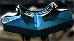
hopefully 2016 will be the year of compact 180 deg.
I could not shape my lenses properly with my poor mans tools. So I decided to take the longest road (almost as long as the Road 66) by making a new heavy duty x-y rotative milling-grinding-polishing-machine.
I could not shape my lenses properly with my poor mans tools. So I decided to take the longest road (almost as long as the Road 66) by making a new heavy duty x-y rotative milling-grinding-polishing-machine.
You do not have the required permissions to view the files attached to this post.
Full immersive research:
HMD:
SONY HMZ-T1
FOV: 40° diagonal
HMD project:
FOV: >180°
Link: http://www.mtbs3d.com/phpBB/viewtopic.php?f=26&t=14332
HMD:
SONY HMZ-T1
FOV: 40° diagonal
HMD project:
FOV: >180°
Link: http://www.mtbs3d.com/phpBB/viewtopic.php?f=26&t=14332
-
cybereality

- 3D Angel Eyes (Moderator)
- Posts: 11407
- Joined: Sat Apr 12, 2008 8:18 pm
-
piecutter
- One Eyed Hopeful
- Posts: 1
- Joined: Fri Jul 04, 2014 4:16 pm
Re: Compact 180 deg fov HMD's still possible?
Very interesting. Seems we've been following a similar path, you and I. Only I began physically testing with Microvision laser projector, but found them too bright! And also added bulk that the original plan was meant to do away with, so now I'm back to using micro displays out of an HMZ. I'm looking into fixing the brightness problem by overdriving them and using a more efficient heatsink than the ones they came with, which shouldn't be to hard as the originals barely do anything. I'm actually 3D printing bezels to hold the displays and heatsinks now.
Also on the to do list, extensions for the ribbon cables (any input appreciated) and a more open source driver board, if possible. Going to need a little help figuring out that one, as I'm a few notches below EE status.
The long term plan is to have a proof of concept with this and then reiterate with the Sony 1080p displays of the same size. They're a bit more difficult to lay hands on as you can't just cheaply buy something off the shelf and pull them out of it, but I have a source that's willing if I pony up for more than I need. Maybe a group purchase if I can find enough interest.
Hope to hear something good from your latest grinding endeavor!