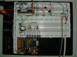
I made a circuit to use my system with DVI connexion.
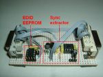
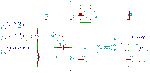
The circuit is composed of two sub-circuit : A EDID (Extended display identification data) EEprom and the Sync extractor :
If I connect my optoma projector directly on DVI, the 3D vision driver switch immediately in discover mode.
I had to wire an I2C EEprom on the DDC data and clock pins, the EDID on the EEprom replace the EDID of the projector and fool the 3d vision driver that believe there is a compatible display connected.
This part might also interest those who have problems with not available resolution/refresh rate.
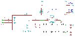
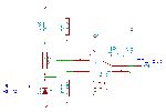
The second part is the Sync extraction circuit, it extract a single sync pulse out of the DVI blue signal.
It works like this :
DVI blue signal :
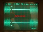
Signal A : Blue-
Signal B : Blue+
The sync pulse is extracted from the Blue signal with a transistor based differential amplifier (signal "RB")
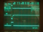
The signal is then shifted by C3, R11 and R4 just above the 555 trigger level (VCC/3).
During a sync pulse, the signal goes below VCC/3 and trig the 555 monostable.
The result is a positive pulse (signal "B").
The circuit works fine, but I have an other problem. There is some flashing dots on the black area of an image even if I plug the projector directly on the video card, without my circuit in between.
This problem doesn't appear on my LCD monitor.

Is someone already resolved this problem ?