[DIY] Universal sutterglasses controller

Tutorials on how to create your own rigs, pics, movies, and everything that has to do with S-3D at home!
User avatar
Petrus
Two Eyed Hopeful
Posts: 95
Joined: Thu Mar 04, 2010 12:50 pm
Location: France

[DIY] Universal sutterglasses controller

Post by Petrus »

To use the 3D vision glasses upside up or different glasses with my 85Hz DLP projector, I built my own sutterglasses controller.
It synchronises with the Nvidia 3DVision emitter and vertical sync signal on the VGA port for more precision.
Here is the wiring diagram of my 3D system :
Image

The color corrector is described here :
http://www.mtbs3d.com/phpBB/viewtopic.php?f=26&t=6054" onclick="window.open(this.href);return false;

The controller currently works with Nvidia, Xpand X101 and vesa glasses like the Elsa wired glasses.
It features a delay and dark time adjustment with 3D vision glasses.

For the moment, I use the scroll wheel and buttons of an old mouse to change the settings :
Image
The scroll wheel increase and decrease the setting displayed on the LCD, the two buttons of the mouse are for next and previous parameter, and the middle button is a shortcut to reverse the 3D.
All the circuit is build around an Atmega8 microcontroller, but I will switch to an Atmega 16 in the future to get an additional interrupt for the remote control.
Image

For the moment it is not very good-looking but I will also work on this :)

[edit]
Schematic :
Picture
kicad file

Source code :
Controller software
3Dvision simulator

[update]
I've made some photos of the finished universal emitter :
Image Image Image Image

The small circuit between the rear panel and the main board is an optional circuit that toggle the power ON and OFF.
I switches the emitter ON after a push on the white button on the rear and it allow the emitter to switch itself OFF after 30min of inactivity or by selecting the off function on the LCD.

Source, schematic & PCB :
Image

Software improvements :
- Buttons are filtered
- LCD backlight management
- OFF function and Auto-off after 30 min (need power switch circuit).
Last edited by Petrus on Mon Jan 10, 2011 3:52 pm, edited 3 times in total.
User avatar
cybereality
3D Angel Eyes (Moderator)
Posts: 11407
Joined: Sat Apr 12, 2008 8:18 pm

Re: [DIY] Universal sutterglasses controller

Post by cybereality »

Wow! Nice work.
mickeyjaw
Cross Eyed!
Posts: 131
Joined: Sun Feb 15, 2009 12:50 pm

Re: [DIY] Universal sutterglasses controller

Post by mickeyjaw »

Nice...

What are you coding this in - ASM or C?

Am i right in believing you could (in the long run, with some code changes) use this to implement a straight VGA pass-thru controller with variable dark time/delay? If so I may build one of these to use instead of an e-dim dongle. Do you intend on posting code and schematics?
User avatar
Petrus
Two Eyed Hopeful
Posts: 95
Joined: Thu Mar 04, 2010 12:50 pm
Location: France

Re: [DIY] Universal sutterglasses controller

Post by Petrus »

I code in C using Winavr.
I already syncronize with the VGA port, but I need the Nvidia emitter informations to know which side of the glasses I need to activate. I don't know how this is achieved with the e-dim dongle.

The dark time can be adjusted only if the glasses has this feature. 3DVision does, Elsa glasses and Xpand X101 doesn't, they have only 2 states, left or right.

I will post the schematic and source code once I get the circuit working with the Atmega16.
User avatar
Likay
Petrif-Eyed
Posts: 2913
Joined: Sat Apr 07, 2007 4:34 pm
Location: Sweden

Re: [DIY] Universal sutterglasses controller

Post by Likay »

The e-d dongle uses the ddc-pin for l/r identification. The later e-d dongles also supports blue-line coding.
Mb: Asus P5W DH Deluxe
Cpu: C2D E6600
Gb: Nvidia 7900GT + 8800GTX
3D:100" passive projector polarized setup + 22" IZ3D
Image
User avatar
Petrus
Two Eyed Hopeful
Posts: 95
Joined: Thu Mar 04, 2010 12:50 pm
Location: France

Re: [DIY] Universal sutterglasses controller

Post by Petrus »

OK, so no problems with the DDC pin, it's way more simple than reading the IR pulses of the 3D vision emitter.
My firsts programs used DDC signal with the old school Nvidia driver.
But for the blue-line coding it sounds like it will need additional hardware and software.
User avatar
Petrus
Two Eyed Hopeful
Posts: 95
Joined: Thu Mar 04, 2010 12:50 pm
Location: France

Re: [DIY] Universal sutterglasses controller

Post by Petrus »

I made the schematic of the controller based on an Atmega16 :
Picture
kicad file

I need to improve the IR led driving circuit as it is not very efficient.

And here is the source code, the Win AVR project and the VMLAB project to simulate the software :
Controller software

To fully simulate the software, you need this VMLAB project that simulate the 3Dvision IR pulses :
3Dvision simulator

If you modify the code or the schematic, please report it on this thread, so everybody can benefit of your improvements.
User avatar
tritosine5G
Terrif-eying the Ladies!
Posts: 894
Joined: Wed Mar 17, 2010 9:35 am
Location: As far from Hold Display guys as possible!!! ^2

Re: [DIY] Universal sutterglasses controller

Post by tritosine5G »

Im very interested if you notice any degradation of brightness and contrast once going stereoscopic 85hz.

120hz is twice dark and contrast is gone too.
-Biased for 0 Gen HMD's to hell and back must be one hundred percent hell bent bias!
User avatar
Petrus
Two Eyed Hopeful
Posts: 95
Joined: Thu Mar 04, 2010 12:50 pm
Location: France

Re: [DIY] Universal sutterglasses controller

Post by Petrus »

Schematic and software update

I've updated the schematic with an efficient IR emitter circuit and some pin changes.
For the moment, the ir emitter circuit is soldered on a separate board to avoid the poor contacs of the bread board. It can accept up to 10 leds, but 6 seems to be sufficient.
Image

I've also made many improvement on the software :
- 85/120HZ test function
- Parameters storage on EEprom
- Synchronizing method is greatly improved

There is also a new function that shut off the emission when a IR command from a remote control is detected. This allow the use of an infrared remote control for other appliances, but it doesn't work with all remote controls because it detects a long start bit and some have a too short startbit.

The links to the updated files and schematic are on the first post.
lish
One Eyed Hopeful
Posts: 31
Joined: Mon Jan 18, 2010 6:16 am
Contact:

Re: [DIY] Universal sutterglasses controller

Post by lish »

Petrus wrote:Schematic and software update

I've updated the schematic with an efficient IR emitter circuit and some pin changes.
For the moment, the ir emitter circuit is soldered on a separate board to avoid the poor contacs of the bread board. It can accept up to 10 leds, but 6 seems to be sufficient.
Image

I've also made many improvement on the software :
- 85/120HZ test function
- Parameters storage on EEprom
- Synchronizing method is greatly improved

There is also a new function that shut off the emission when a IR command from a remote control is detected. This allow the use of an infrared remote control for other appliances, but it doesn't work with all remote controls because it detects a long start bit and some have a too short startbit.

The links to the updated files and schematic are on the first post.
Good job.
Is anybody hack the 3D shutter of Samsung? The shutter of Samsung is too expensive.... :roll:
OzOnE2k10
Sharp Eyed Eagle!
Posts: 436
Joined: Wed Jan 13, 2010 7:12 am
Location: UK

Re: [DIY] Universal sutterglasses controller

Post by OzOnE2k10 »

Petrus, this is excellent stuff!

I thought I'd play around with some 3D stuff again (I recently got hold of a 43" Pioneer plasma TV that I want to test 3D on - unfortunately it's 60Hz only). I then saw your posts and it inspired me again. :)

I've already spent a LOT of time messing with code and PCB layouts for a universal controller, but I never got around to finishing it. This was mainly because the PIC chip I was using just isn't fast enough to allow blue-line decoding to work properly at all resolutions.

I also thought about a "color-flipping" method for DLP projectors to increase the shutter rate of the glasses and reduce flicker. Actually, "iondrive" thought of this idea first, but I did manage to get it working to an extent...

It worked great for reducing flicker, but the problem was that the image from my Acer projector was then too dark. This is mainly because it uses a 4x colour wheel and my cheap Elsa glasses were too slow to keep up. It work probably work well with 60Hz projectors with 2x colour wheels but would also require modified software (Iz3D etc).

You can read more of my experiments here (warning, LONG posts!!)...

http://www.mtbs3d.com/phpBB/viewtopic.php?f=3&t=5458" onclick="window.open(this.href);return false;

@Petrus - I was basically wondering if we could work together on a universal glasses controller by combining the features of your design with blue-line decoding etc?

I also made a start on some PCB layouts and connection ideas a few months back. I don't have much experience with AVR chips, but I can read C code pretty well now and it would be a great opportunity for me to learn some AVR stuff (and move away from most of the assembly programming I used on PICs previously).

Ideally, I wanted to use a small FPGA or CPLD chip to do the blue-line decoding, but I couldn't find a cheap enough solution. I'm sure AVR chips are better suited to the task because they don't seem to divide the master clock down as much as PICs do.

All it needs to do is to count the H/V sync pluses to find the last line, then count the length of the blue line. This worked up to a point on the PIC, but the line counting routine was always a few lines away from where it should be (because the horizontal sync pulses appear to happen during VSYNC, so my interrupt routine didn't capture them properly).

My code also didn't work for different resolutions because of the lack of precision on the PICs timers (which I was using for line counting). I have to manually change a divider value in the code to get different resolutions to work.

If you know any tricks for getting line counting working correctly, the rest of the blue-line code is fairly simple.

Your code is very well commented and already has many of IR protocols - if blue-line decoding was added then you could keep L/R sync without the need for the nVidia emitter. It should then work great with the Iz3D drivers and Stereoscopic Player (possible 3D Blu-Ray support in future?).

What do you think?

OzOnE.
User avatar
Petrus
Two Eyed Hopeful
Posts: 95
Joined: Thu Mar 04, 2010 12:50 pm
Location: France

Re: [DIY] Universal sutterglasses controller

Post by Petrus »

I had also issues with bit planes when my controller was'nt properly adjusted.
I first used a simple 100% black 100% white test pattern that resulted in color artefacts, but now I use thoses:
Image Image

I recorded the bit planes on my 85HZ DLP projector using a photodiode and oscilloscope :
http://www.mtbs3d.com/phpBB/viewtopic.php?f=26&t=6054" onclick="window.open(this.href);return false;

I see what you're trying to do, but i don't think it will work.
Even if you can trig the shutterglasses exactly after the MSB bitplane, the LCDs obturators will be too slow an you will loose some of the next bitplanes.
The fastest glasses I measured is the Xpand X101 :
Ton :600µs
Toff (100-10%) :1,54ms

As you can see on my oscillograms, you will loose some color data. What are the results with my test patterns on your system ?

For the blue-line coding, as it is time critical, it is preferable to use an other microcontroller for that purpose and send a TTL signal to the universal controller.
Some AVRs are designed to work at 20MHz. I also managed to overclock a 16Mhz Atmega8 to 24MHz.
OzOnE2k10
Sharp Eyed Eagle!
Posts: 436
Joined: Wed Jan 13, 2010 7:12 am
Location: UK

Re: [DIY] Universal sutterglasses controller

Post by OzOnE2k10 »

Hi, thanks for the reply...

I stopped trying to swap bit planes because simply swapping the green channel between the Left / Right images worked quite well.

I actually got the Colorflipping mode working (flicker was hugely reduced and 3D depth was much better). The only problem was that the image was fairly dim on my projector when Colorflipping was enabled...

This is due to my projector having a 4x colour wheel which meant the effective shutter rate of the glasses increased to around 210Hz!! I tested it with Elsa glasses, so I see now from your test bench results that the Toff period of 4.56ms is almost as slow as the 210Hz period of 4.76ms. The glasses just can't keep up!

So, for people with fixed 60Hz projectors and 2x or 3x colour wheels, Colorflipping might still be an option for big improvements in S3D. A 2x colour wheel projector would give around 105Hz shutter speed and a 3x colour wheel would give around 157.5Hz shutter speed (dependant on the color segment config of course).

I do admit that the coding might be a bit of a pain though - The controller would need to detect the start of each colour segment with a photodiode to program it for different projectors. This will be far easier in C though. (At the moment, I have to manually code the timings for my projector.)

I might come back to the Colorflipping idea at some point, but right now I'm building an improved controller based on your project so thanks again for making your schematics and code available!...

I literally just got an ATmega16 yesterday and I'm just messing with your code under AVR Studio. I'm starting to add the blue-line stuff but I've never used an AVR chip before. I just need familiarize myself with the datasheet and the different registers / timers etc. I'm sure the ATmega will work better than the PIC I was using since the PIC ran at Fosc / 4 (only 5MHz internally with a 20MHz crystal).

The only problem with blue-line decoding on the old PIC controller was due to lack of timer precision. It did work fine at a fixed resolution though.
I probably could have fixed it, but coding in C on the AVR is already SOOOOO much quicker and nicer. :D (I always used PIC assembly before).

I'll probably need to disable the nVidia IR receiver (or IR remote) stuff when blue-line decoding is enabled because I need to use the timers.

The code for counting the lines is fairly simple and is already working under Proteus VSM, I just need to use a timer to find the center of the last line, then use the comparator to detect the blue line.

btw, I just bought my first pair of wireless glasses (Samsung SSG-2100AB), do you know any tricks for finding the IR protocol as I don't have an emitter or 3DTV? Using a Gameboy seems to be an excellent solution, I'll have to give it a go... :lol:

http://furrtek.free.fr/index.php?p=crea&a=xpand&i=2" onclick="window.open(this.href);return false;

I also don't have a decent display yet (hence the Colorflipping experiments). I thought I'd give the Samsung glasses a try with Colorflipping first, then maybe buy an 85Hz projector.

EDIT: Forgot to say about the colour quality. It actually looked pretty good even when Colorflipping was enabled. I did use similar colour bar patterns to yours for testing the ghosting / delays and I didn't notice any major problems. I'm guessing the colour differences are mainly down to the differences in colour wheel configuration.

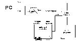
My projector is fixed at 60Hz though - am I correct in saying that your projector is doing 1.5 revs of the colour wheel per frame? Like in this PDF (page 6)...

http://cmst.curtin.edu.au/local/docs/pubs/2007-05.pdf" onclick="window.open(this.href);return false;

Your Optoma EP739 is on the compatibility list and it says that "many of the projectors which work at 85Hz actually drop the colour wheel speed down to 1.5x". This would explain the differences you're seeing in colour quality on alternate frames. Your solution to the problem was very clever though. ;)

btw, I loved your DVI sync extractor! I didn't think it would be possible without a far more complex circuit or FPGA and I'm stunned that it was so simple. I have many questions to ask you about this, but I'll save it for another post.

OzOnE.
P.S. I think I spotted a small typo in "emit_v12.c" line 406. cons_delay_p = cons_delay_p; :)
User avatar
tritosine5G
Terrif-eying the Ladies!
Posts: 894
Joined: Wed Mar 17, 2010 9:35 am
Location: As far from Hold Display guys as possible!!! ^2

Re: [DIY] Universal sutterglasses controller

Post by tritosine5G »

Check this out, scroll down to DLP part.
http://www.hewletts.org/2007_08_01_archive.html" onclick="window.open(this.href);return false;
no problem the hacker's site is blocked, practically there was nothing there, little progress, dead (filehost) mirrors.
Reading about the DLP developer guy, I sincerely wish he'd get better!!

I too have to learn about this DLP color thing:
http://patft.uspto.gov/netacgi/nph-Pars ... nstruments" onclick="window.open(this.href);return false;
http://appft1.uspto.gov/netacgi/nph-Par ... %2FGregory+" onclick="window.open(this.href);return false;
-Biased for 0 Gen HMD's to hell and back must be one hundred percent hell bent bias!
OzOnE2k10
Sharp Eyed Eagle!
Posts: 436
Joined: Wed Jan 13, 2010 7:12 am
Location: UK

Re: [DIY] Universal sutterglasses controller

Post by OzOnE2k10 »

Hi, tritosine,

I don't want to hijack Petrus' thread for long because I could talk about the DLP subject for hours. I'll TRY to keep it short...

I exchanged e-mails with George Hotz about four years ago. This was before he went on to do the amazing hacks on the PS3 and iPhone.

At the time, I was working on reverse-engineering an old Proxima DS1 projector when I came across his DLP project (just happened to be the same projector that George took his SVGA DMD chip from!).

I added high-power RGB LEDs to the Proxima to replace the lamp / colour wheel. In the process, I also learnt a huge amount about DLP because I wanted to change the bit plane order to speed up the colour frequency of the LEDs (to reduce the rainbow effect etc.).

Here's one of the few files I found which actually describes the software which TI used to setup the bit plane stuff on some of the first DLP projectors (outdated now)...

http://www.google.co.uk/url?sa=t&source ... i89sOaDF9Q" onclick="window.open(this.href);return false;

I never did manage to change to a custom bit-plane config on the Proxima - Working out how to alter the bit-plane loading delays as well getting the reset delays to match was too difficult (without having the original software or more info about the codes).

George was kind enough to send me his DLP project files. His code is quite complex though, and it would be tricky to solder the Xilinx FPGA which he used unless you have a reflow "toaster oven".

Having said that, with the info which George released it should now be fairly simple to control a DMD chip directly. You could do it with a smaller FPGA, some DRAM, and a DAD1000 type DMD reset chip. The age-old problem for me (apart from lack of funds) has always been getting PCBs made, otherwise it's not as difficult as you might think to get it working.

Building my own custom DLP projector is yet another in a long line of projects that I'll probably never get around to doing. This would of course be the "killer app" for DIY S3D projection and for ALL sorts of other improvements (cheaper 3-chip projectors / much higher refresh rates / custom 3D modes etc).

Anywho, if anyone would like a copy of George's DLP project files, please drop me a PM. I'm sure George won't mind (the project files were originally made public before the servers / blog got changed around.)

He has made quite a name for himself since the DLP stuff!... :)

http://www.youtube.com/watch?v=Wh3VqA1sp40" onclick="window.open(this.href);return false;

OzOnE.
P.S. The AVR chip has been a huge pain today. I was able to program the chip fine and it appeared to be running, but the LCD just wouldn't display properly. After much messing around with PonyProg and the fuses, the chip appears to have died! :( I'll just buy another one I think.
EDIT: Chip is still alive! Yep, was a fuse set wrong. Had to use a TTL oscillator to get it running again. LCD still not working though.
User avatar
tritosine5G
Terrif-eying the Ladies!
Posts: 894
Joined: Wed Mar 17, 2010 9:35 am
Location: As far from Hold Display guys as possible!!! ^2

Re: [DIY] Universal sutterglasses controller

Post by tritosine5G »

The age-old problem for me (apart from lack of funds) has always been getting PCBs made, otherwise it's not as difficult as you might think to get it working.
As long as it is darkchip3 , I dont care how hard is it :mrgreen:

I told this to Petrus too, but Im telling you now. I can get you PCB's made, I think I can get reflow stuff, and I know 3 ppl skilled with professional layout SW
I think I can get DLP chips from a repairman.

LED luma: http://readalert.atw.hu/THE_ULTRA_HIGH_GAIN_SCREEN.pdf ;)
PowerLEDs could be used to simulate an "iris" as well . Contrast would be killer, and the hardware brightness slider ... hmmmmmmmmmmm!!!!!! :oops: (im in love)

After using this 120hz DLP for a while. I can safely say , we want no more than 120hz. Thats as purrfect as it gets, still pictures, screenshots , purrfect. Rainbow is gone for me, others say its there, but its a very distant memory to me. Actually, we'd want less refresh rate , because sustaining 120fps in games is quite hard , and 50hz vsync would be way easier , hence 100hz shuttering. 150 Usd gfx hardware does that easily!!

ps.: Im prepared to sell ALL my vintage audio stuff to fund this project . :twisted:

EDIT: forgot I can get you switch mode power supplies in all shapes & sizes ;)
Last edited by tritosine5G on Mon Aug 30, 2010 3:32 pm, edited 1 time in total.
-Biased for 0 Gen HMD's to hell and back must be one hundred percent hell bent bias!
User avatar
Petrus
Two Eyed Hopeful
Posts: 95
Joined: Thu Mar 04, 2010 12:50 pm
Location: France

Re: [DIY] Universal sutterglasses controller

Post by Petrus »

The IR receiver code uses an 8-bit timer (Timer2) does it is precise enough for decoding the blue-line ?
The 16-bit timer is used for delay adjustment and IR emission.

The game boy thing isn't fast enough to record the IR pulses, just compare what the game boy recorded and what I've recorded of the Xpand X101 ir pulses : http://www.mtbs3d.com/phpBB/viewtopic.php?f=26&t=10169" onclick="window.open(this.href);return false;

I tried to record the pulses of a Samsung 3D TV in a store, but my pulse-recorder is too sensitive to interferences and all I got is random data. I need to make the photodiode amplifier less sensitive to get the IR protocol of demo TVs.

Yep, the colorwheel makes 1.5 rotation per frame at 85Hz on my Optoma EP739. I have to disable the equivalent of more than 1/2 of the colorwheel to get a correct picture. The clear segment is disabled on the projector's menu and an other segment is disabled by closing both shutters of the glasses, or with my VGA color corrector if the glasses can't do this (ex: with Xpand X101)

Fuse bits problems is a big classic with AVRs but they can be set once for ever, unlike PIC microcontrollers as I remember when I used to program them.
On my Atmega16, only The SPIEN and CKOPT fuse are programmed.

Does the test message is sent on the serial output ?

tritosine :
Leds or even better, lasers diodes are the best light sources for both 2D and 3D projector : long life, better color space, adjustable brightness and no colorwheel that explode when you watch 3D demos !
My colorwheel broke with a loud glass-breaking noise last week, fortunately I was able to replace it with an other one from a broken projector.
I had to do some modifications and the new one is noisier than the original, but it works.
OzOnE2k10
Sharp Eyed Eagle!
Posts: 436
Joined: Wed Jan 13, 2010 7:12 am
Location: UK

Re: [DIY] Universal sutterglasses controller

Post by OzOnE2k10 »

Hi,

@tritosine, I've replied on the "DIY DepthQ" thread, 'cos I don't want to threadjack poor Petrus any more.... ;)

http://www.mtbs3d.com/phpBB/viewtopic.p ... 053#p50053" onclick="window.open(this.href);return false;

@Petrus - I finally got the LCD working last night. I should have guessed that it was down to the fuses. What happened was that PonyProg decided to stop working completely as I was updating some fuses (won't detect the parallel port any more??). It reset all the fuses, so JTAG was enabled!!

I should have guessed really, I've read so many posts about problems with fuses on AVRs. The data on the LCD did look a bit strange - I thought that was due to the port switching between input and output, but it was actually the JTAG screwing things up!

I also learnt pretty quickly that SPI programming doesn't work without a master clock. :( I had to use a 4MHz TTL clock temporarily until I got the fuses sorted.

I'm now programming the chip directly using WinAVR (Programmer's Notepad). I just use the "bsd" type pinout on the parallel port which is supported by avrdude.

Anyway, it's sorted now - I've added a rotary encoder and it's working fine. I also modified your code slightly so that it only updates the LCD when a screen or value changes. This should cut down on a few instruction cycles and possibly some electrical noise.

I'll probably start adding the blue-line stuff tonight. An 8-bit timer should be precise enough as long as the divisor can be set so that we can measure the length of the video lines, then find the center of the last line. This did cause a problem on the PIC though, but it should be possible to just increment a separate counter every time the timer overflows instead (to get more precision).

Actually, that's not a bad idea. The timer is running anyway, so just need to increment a counter on each overflow, then backup the counter and reset it on each Hsync pulse. Then, on the last line, just divide the backup value by 2 to find the middle (backup value will have come from the previous line).

I also need to add a pot for the comparator to give the voltage reference for detecting the Blue signal. A diode should be a nice voltage source.

It's a shame about the Samsung glasses. I should receive mine tomorrow, so I'll have to build a quick data logger and grab the IR pulses somehow.

OzOnE.
P.S. I can't believe your colour wheel broke like that. :o
I hate colour wheels with a passion, hence the LED projector project. We won't get rid of the rainbow effect unless the DMD project works though. :geek:
User avatar
Petrus
Two Eyed Hopeful
Posts: 95
Joined: Thu Mar 04, 2010 12:50 pm
Location: France

Re: [DIY] Universal sutterglasses controller

Post by Petrus »

There is some issues with parallel port and Windows XP, look at the end of the page :
http://www.aplomb.nl/TechStuff/PPPD/PPPD%20English.html" onclick="window.open(this.href);return false;
OzOnE2k10
Sharp Eyed Eagle!
Posts: 436
Joined: Wed Jan 13, 2010 7:12 am
Location: UK

Re: [DIY] Universal sutterglasses controller

Post by OzOnE2k10 »

I forgot to mention that I'm actually on Win 7 now (I know, don't say it) :oops:

99% of programs I run on Win 7 are working fine. It was only PonyProg which seemed to have a problem. WinAVR / AVRstudio / avrdude are working great atm.

The "giveIO" driver is installed and all my other EPROM programmer software works on the parallel port too? As long as avrdude stays working, I should be cool.

OzOnE.
OzOnE2k10
Sharp Eyed Eagle!
Posts: 436
Joined: Wed Jan 13, 2010 7:12 am
Location: UK

Re: [DIY] Universal sutterglasses controller

Post by OzOnE2k10 »

Hi,

The new controller isn't going too well. :(

I actually managed to get blue-line decoding working to some extent, but it still only works in certain resolutions. The main issue is due to the problem of finding the last visible line - for XGA for example, the controller actually counts 806 lines instead of 768. This is because it's counting the extra Hsync pulses during the Vsync pulse + "back porch" + "front porch".

To find the last visible line for XGA @ 60Hz, I need to subtract 9 from the Hsync count (sync pulses + front porch?). The blue-line decoding works, but with many glitches. Something appears to upset the frame sync after several frames - I haven't found if it's PC related yet.

How on Earth am I supposed to calculate which line the last visible line is on?? :? If this can be done fairly simply then there might be a chance to iron out the other problems. I have no idea how they calculate this inside LCD monitors?

It might just need a lookup table if all VGA resolutions are VESA standard? Or, I could try adding a routine which scans for the last visible line / blue line?

You're probably right though, Petrus - without an external IC to do blue-line decoding, it might be impractical to do everything on the AVR. With the visible line problem, it would be difficult enough on an FPGA.

A nice tip for debugging the code btw - I just connect an output pin from the AVR to the Green VGA channel via a resistor. That way, I can actually "see" on the monitor when a specific routine is being executed and when the middle of the last line is found etc. There may be a very small risk to the graphics card when doing this, but with a large enough resistor I can't see it being a problem (I use around 1.5K).

For the time being I can use the controller for simple Vsync toggling. Hopefully I will find a way of grabbing the IR protocol for my Samsung glasses.

Petrus - does your IR analyser record the serial stream to the MP3 recorder? If you don't mind me asking, what format / baud rate is the serial stream? Does it start from 0us when the recording is started, then log each time an IR pulse is found? (does it continuously increment the timer until it wraps, or do you try and reset it every few frames?)

Please let me know if the latest blue-line code is of any use to you - I know it's not working properly yet, but it should be fairly easy to add to the controller if I can get it working. Another small problem with the code is that it uses INT1 for Hsync, and the INT2 pin is currently being used for the comparator input. This might require a manual switch to allow IR reception and the other original design features.

I found that blue-line decoding worked only when I enabled the compare counter on the last line, then disabled the compare interrupt right after testing the blue-line with the comparator. If I didn't do that, the compare int would re-trigger for some reason?

I'll carry on coding though. I really want this to work using the minimum number of ICs if possible. It will be an ultimate universal controller if we can find a reliable 3D sync method which doesn't rely on extra commercial hardware (apart from a nice pair of glasses maybe :shutter ).

OzOnE.
User avatar
Petrus
Two Eyed Hopeful
Posts: 95
Joined: Thu Mar 04, 2010 12:50 pm
Location: France

Re: [DIY] Universal sutterglasses controller

Post by Petrus »

I cant help for the blue-line coding, I don't know anything about it.

My Ir pulse recorder is triggered with the first detected pulse and record the timings of following pulses during 20ms, send the data on the serial output @ 2400bauds and restart a new cycle.

I can give you the code but it will need some correction, it is quite buggy when used with a noisy input.
It send data in this format :

Code: Select all

Temps(us),Etat,Tpulse/Tpause(us),Descr
0,0,,
1,1,,
13,1,,
14,0,14,Pulse0:pulse
29,0,,
30,1,16,Pulse0:pause
44,1,,
45,0,15,Pulse1:pulse
63,0,,
64,1,19,Pulse1:pause
78,1,,
79,0,15,Pulse2:pulse
The first column is the time in µs, the second is the state, the third is the pulse or pause duration and the last is the description of the 3rd column.
Only 1/2 line are real measurement, the others are only here to plot the pulses on excel.
OzOnE2k10
Sharp Eyed Eagle!
Posts: 436
Joined: Wed Jan 13, 2010 7:12 am
Location: UK

Re: [DIY] Universal sutterglasses controller

Post by OzOnE2k10 »

Oh, I see now. I was wondering how you would reset the timing :) (otherwise the count would need to wrap at some point).

I'll see if I can put something together that's small enough for me to take into a shop and grab the Samsung protocol. I was thinking of putting a sensor down my sleeve, that way I can put it really close to the IR emitter.

The staff in the shop would probably let me try me own glasses if I told them I was interested in what the different TV's were like. I could then make out I was trying to find where the emitter is by blocking it with my hand. We only need a few seconds of decent IR output. :lol:

Then again, I'd probably just try and grab the protocol anyway first in case they get suspicious.


As for the controller - if I can stop the jitter problems with the Hsync pulse counting, I might be able to get the blue-line code to automatically find the last visible line. There is only a range of around 15 lines which it would need to scan from the bottom-up. I would then need to see if the blue line is toggling on alternate frames (I did something similar with the old PIC code to generate a "blueline_valid" flag.

I'm still hopeful, but it will take me a long time to get it working reliably. I just need to find some motivation in the next few days.

btw, I found a really cheap 2-Way HDMI manual switch-box in a supermarket (£1 each). They would make a nice housing for the shutterglasses controller if nothing else. I was wondering though - would it be very difficult to also extract the Hsync timing from the DVI / HDMI channel? I'm guessing it would need some type of PLL circuit to time the Hsync pulses during the very short Vsync pulse??

I will probably use your sync extractor for simple Vsync toggling though, I still can't believe what an elegant solution it is. ;) I would like to stop using VGA altogether if I can get DVI / HDMI working with the controller.

OzOnE.
User avatar
Petrus
Two Eyed Hopeful
Posts: 95
Joined: Thu Mar 04, 2010 12:50 pm
Location: France

Re: [DIY] Universal sutterglasses controller

Post by Petrus »

Vsync is easy to extract because the pulses are much longer than the short data pulses.
Hsync pulses will be much more difficult to extract, I didn't see them with my oscilloscope.

For the moment I'm stuck with VGA too, my projector display parasites when I use it with the DVI input.
With my older PC the picture is perfect but with the one I play 3D videos and games there is parasites on the picture.
I noticed that the DVI signal is stronger on my old PC. Is there different DVI norm ?
OzOnE2k10
Sharp Eyed Eagle!
Posts: 436
Joined: Wed Jan 13, 2010 7:12 am
Location: UK

Re: [DIY] Universal sutterglasses controller

Post by OzOnE2k10 »

OK, that's what I thought - it's probably not worth the effort trying to extract Hsync from DVI without a proper receiver chip then.

I'm not sure why some displays don't conform to the DVI standard properly. I have the same problem with my plasma TV. It's a few years old, but one of the "industrial" models... If I use my 5-metre DVI cable, it has lots of image corruption and only syncs at XGA. I know the cable works perfectly with everything else, so it must be an impedance issue with the TV (like you mentioned before)?

I did have problems with different graphics cards in the past too - some of them have much more "solid" DVI outputs and work with everything. Other cards are weaker and have problems driving longer / cheap cables. Even VGA outputs vary quite a lot between graphics cards / brands.

I'm going to have to leave the shutterglasses controller project for a while. I need to think about an improved method for blue-line decoding. It seems that the only way to get reliable results is to use a separate chip. I've never used a PAL chip or small CPLD, but I'd imagine this is want I'd need. (Any chip which is small and cheap and can be programmed under Verilog would be easy to get working, I just need to find one.)

When I get around to it, I'll also add some different input modes to the controller menu. Even simple Vsync toggling would be a nice feature if I can just get hold of the Samsung glasses protocol. I'm still working on that problem though. ;)

One annoying thing about the AVR is that is doesn't seem possible to re-assign the positive input of the comparator to a different pin? Otherwise the Int2 pin can't be used? The bandgap reference voltage is too high for blue-line decoding, unless I use an external booster transistor for the "blue" signal? Actually, that might be a good idea anyway - the "blue" signal could be buffered so the AVR doesn't cause interference.

If I can use an external chip to do reliable line-counting then everything else can be figured out on the AVR. The algorithm to find the last visible line should be straightforward - you just keep a "log" of the last 15 (or so) lines to see which was the LAST line to contain any "blue" data. This value updates on each frame and tells the blue-line routine which line to test. It actually sounds more complex than it is, I'll have to try this in the next few days.

As for the DMD stuff - I'm still working on it. I'll just try to make a DMD + Reset board which is as simple as possible and see if Tritosine can help with manufacturing. :D

OzOnE.
User avatar
tritosine5G
Terrif-eying the Ladies!
Posts: 894
Joined: Wed Mar 17, 2010 9:35 am
Location: As far from Hold Display guys as possible!!! ^2

Re: [DIY] Universal sutterglasses controller

Post by tritosine5G »

As for the DMD stuff - I'm still working on it. I'll just try to make a DMD + Reset board which is as simple as possible and see if Tritosine can help with manufacturing.
hey, I can help and I have some free time now too, Im willing to dedicate! First off, I'll do some screen stuff, & wait for a friend to chime in (with his DMD's) , but if you have better idea... :mrgreen:
-Biased for 0 Gen HMD's to hell and back must be one hundred percent hell bent bias!
User avatar
Petrus
Two Eyed Hopeful
Posts: 95
Joined: Thu Mar 04, 2010 12:50 pm
Location: France

Re: [DIY] Universal sutterglasses controller

Post by Petrus »

OzOnE2k10 wrote: If I can use an external chip to do reliable line-counting then everything else can be figured out on the AVR. The algorithm to find the last visible line should be straightforward - you just keep a "log" of the last 15 (or so) lines to see which was the LAST line to contain any "blue" data. This value updates on each frame and tells the blue-line routine which line to test. It actually sounds more complex than it is, I'll have to try this in the next few days.
OzOnE.
If you use an external chip to count lines, why don't use it to do all the blue-line decoding stuff too, and just send a 0-5V signal to the atmega16 ?
I think it will be simpler. And you could plug old style DDC glasses directly on it.
OzOnE2k10
Sharp Eyed Eagle!
Posts: 436
Joined: Wed Jan 13, 2010 7:12 am
Location: UK

Re: [DIY] Universal sutterglasses controller

Post by OzOnE2k10 »

Yep, that would be better I suppose - it's actually the line counting which has the biggest problems. The interrupt routines just aren't quite fast enough to reliably capture all the Hsync pulses during a Vsync pulse.

The only way I can see it working is to count the lines using hardware counters; this should be as simple as inputting the sync signals to the external clock inputs for the timers. That way, there shouldn't be any reason to miss Hsync pulses and you simply backup the Hsync count then reset it on the next Vsync.

The reason I'm a bit obsessed with blue-line decoding is that it is the most generic sync method that can be found in both Iz3D and Stereoscopic Player. This also makes it generic across ATI and nVidia cards as well as bypassing the need for extra (commercial) hardware. It would be great to just have the controller box which is relatively cheap to produce and can control practically any pair of shutterglasses you want (thanks to your generous gift).

I'm starting to wonder if it would be easier to decode a "marked" sync method? This often requires testing of two or more colour channels though.

The tricky thing with finding the last visible line for BL decoding is that it will toggle on / off at each frame (if I only test the center of the line). I'll get there in the end. I'm determined not to let this beat me this time - it's so much nicer having a proper LCD on the board too. :P

I'm in the coding mood atm, so I'll try to get the visible line stuff working.

OzOnE.
P.S. Thanks, Tritosine. I'll try to work on the board layout too as well. So many projects / so little time. 8-)
evgenln
One Eyed Hopeful
Posts: 18
Joined: Tue Sep 28, 2010 5:28 am

Re: [DIY] Universal sutterglasses controller

Post by evgenln »

Hi guys. At present I am working on universal emitter based on CY7C68013A, which will be recognized by the operating system as NVIDIA 3dVision emitter. Many thanks to Petrus for the provided information about the different glasses ir-protocols. I am very interested in SAMSUNG SSG-2100/2200 glasses ir-protocol. Unfortunately I can't grab the desired protocol from the TV.

Code: Select all

Temps(us),Etat,Tpulse/Tpause(us),Descr
0,0,,
1,1,,
13,1,,
14,0,14,Pulse0:pulse
29,0,,
30,1,16,Pulse0:pause
44,1,,
45,0,15,Pulse1:pulse
63,0,,
64,1,19,Pulse1:pause
78,1,,
79,0,15,Pulse2:pulse
Petrus is it what I'm looking for? Could you provide all 20 ms of record for correction and testing.
typhoon
One Eyed Hopeful
Posts: 12
Joined: Tue Sep 28, 2010 11:40 am

Re: [DIY] Universal sutterglasses controller

Post by typhoon »

Hi Petrus, have you tested your controller with the samsung monitor RZ2233 or any other PC monitor 3d vision ready?
I believe that playing with those timings should eliminate the "top/bottom of the screen ghosting" that all LCD monitors are suffering.
Maybe sacrificing some brigthness and increasing the OFF time, or just delaying the signal a bit.
Also about the other kind of ghosting, when there are very high contrast situations...
i'm very curious, do you (or anyone else) have done some tests ?
Thanks :)
User avatar
Petrus
Two Eyed Hopeful
Posts: 95
Joined: Thu Mar 04, 2010 12:50 pm
Location: France

Re: [DIY] Universal sutterglasses controller

Post by Petrus »

evgenln wrote:Hi guys. At present I am working on universal emitter based on CY7C68013A, which will be recognized by the operating system as NVIDIA 3dVision emitter. Many thanks to Petrus for the provided information about the different glasses ir-protocols. I am very interested in SAMSUNG SSG-2100/2200 glasses ir-protocol. Unfortunately I can't grab the desired protocol from the TV.

Code: Select all

Temps(us),Etat,Tpulse/Tpause(us),Descr
0,0,,
1,1,,
13,1,,
14,0,14,Pulse0:pulse
29,0,,
30,1,16,Pulse0:pause
44,1,,
45,0,15,Pulse1:pulse
63,0,,
64,1,19,Pulse1:pause
78,1,,
79,0,15,Pulse2:pulse
Petrus is it what I'm looking for? Could you provide all 20 ms of record for correction and testing.
No, that's not what you looking for, it's just random pulses. I don't have Samsung Ir protocol.
typhoon wrote:Hi Petrus, have you tested your controller with the samsung monitor RZ2233 or any other PC monitor 3d vision ready?
I believe that playing with those timings should eliminate the "top/bottom of the screen ghosting" that all LCD monitors are suffering.
Maybe sacrificing some brigthness and increasing the OFF time, or just delaying the signal a bit.
Also about the other kind of ghosting, when there are very high contrast situations...
i'm very curious, do you (or anyone else) have done some tests ?
Thanks :)
I don't have any 120Hz LCD to test it.
evgenln
One Eyed Hopeful
Posts: 18
Joined: Tue Sep 28, 2010 5:28 am

Re: [DIY] Universal sutterglasses controller

Post by evgenln »

But you tried to record the pulses of a Samsung 3D TV in a store? Could you provide this record, if it persists, I will try to extract some useful information.
For me it's the only way to ask someone else record SAMSUNG ir-pulses, the reason is that in a place where I live, there are no stores or demo rooms with these TVs.
User avatar
Petrus
Two Eyed Hopeful
Posts: 95
Joined: Thu Mar 04, 2010 12:50 pm
Location: France

Re: [DIY] Universal sutterglasses controller

Post by Petrus »

OK, if you insist, here are the data of my recordings :
http://www.megaupload.com/?d=6PKBMUOA" onclick="window.open(this.href);return false;
http://www.megaupload.com/?d=YEF24C31" onclick="window.open(this.href);return false;

Open them with Notepad++ to get the correct format.
And if you achieve to find the protocol, post it on the forum.
Good luck ;)
User avatar
tritosine5G
Terrif-eying the Ladies!
Posts: 894
Joined: Wed Mar 17, 2010 9:35 am
Location: As far from Hold Display guys as possible!!! ^2

Re: [DIY] Universal sutterglasses controller

Post by tritosine5G »

I believe that playing with those timings should eliminate the "top/bottom of the screen ghosting" that all LCD monitors are suffering.
Maybe sacrificing some brigthness and increasing the OFF time,

-you mean sacrificing some *more* brigthness ? They are already doing it ;) LBRB shuttering instead of LRLR
-Biased for 0 Gen HMD's to hell and back must be one hundred percent hell bent bias!
evgenln
One Eyed Hopeful
Posts: 18
Joined: Tue Sep 28, 2010 5:28 am

Re: [DIY] Universal sutterglasses controller

Post by evgenln »

Sorry for the trouble Petrus but I must ask you some questions about log content.
1. You wrote that your logger makes entries of 20 ms but I see in the first column value about 65000. Tell me please, Is logs record interval 65 ms or 1 is equal to 0.3 us?
2. The values of digits in the first column followed by no increase (in the chapels of one measurement). This means that they simply are not sorted or over a long period there was no pulse?
User avatar
Petrus
Two Eyed Hopeful
Posts: 95
Joined: Thu Mar 04, 2010 12:50 pm
Location: France

Re: [DIY] Universal sutterglasses controller

Post by Petrus »

As I said, The recorder is a bit buggy, now you just know why :)
The resolution is 1µs, 1 increment = 1µs
User avatar
Petrus
Two Eyed Hopeful
Posts: 95
Joined: Thu Mar 04, 2010 12:50 pm
Location: France

Re: [DIY] Universal sutterglasses controller

Post by Petrus »

I think I will rebuild the IR recorder and make a tour on a TV store to record some 3D glasses IR protocols.
Does someone have a schematic of a photodiode amplifier that is not too sensitive and doesn't saturate when the photodiode is very close to the emitter ?
I need something that can record IR puses from 0 to 1 meter away from the IR emitter.
AWoods
SD&A Co-Chair
Posts: 57
Joined: Sat Dec 22, 2007 3:38 am

Re: [DIY] Universal sutterglasses controller

Post by AWoods »

Petrus wrote:I think I will rebuild the IR recorder and make a tour on a TV store to record some 3D glasses IR protocols.
Does someone have a schematic of a photodiode amplifier that is not too sensitive and doesn't saturate when the photodiode is very close to the emitter ?
I need something that can record IR puses from 0 to 1 meter away from the IR emitter.
Just put a filter over the sensor which provides some filtering in the IR wavelengths.
I wonder if a crossed polariser might work at this wavelength.
Or perhaps put an aperture (a pin hole?) over the sensor.

Keep up the good work!

A.
evgenln
One Eyed Hopeful
Posts: 18
Joined: Tue Sep 28, 2010 5:28 am

Re: [DIY] Universal sutterglasses controller

Post by evgenln »

Тry here this scheme http://www.botskool.com/images/elec/lf10.JPG. And as AWoods said filter from an old remote control or red glass, removes some noise.
User avatar
Petrus
Two Eyed Hopeful
Posts: 95
Joined: Thu Mar 04, 2010 12:50 pm
Location: France

Re: [DIY] Universal sutterglasses controller

Post by Petrus »

The sensor I used is already IR filtered (Black case).
Thanks for the schematic evgenln, but this one is too slow.
I finally reverse-engineered the photodiode amplifier on Xpand X101 glasses, simplified and modified it to adjust the sensitivity.
Post Reply

Return to “Do it Yourself!”