Is yours set on 3.3V on the jumper?zacherynuk wrote:And I can confirm with both a similar DVI small board and the 7-in1 I use a 12v 1500ma - So it looks like your multi PSU isn't supplying enough juice.Dycus wrote:Yoder - I've used that driver. It needs 12v DC, positive tip, at around 1A (You could get away with 700mA, though). Don't connect it backwards or you'll fry your screen's backlight driver (trust me, I'd know...). Make sure the driver's jumper is set to 3.3v. If it doesn't work after that, I'd say it's either a faulty cable, driver, or screen.Really narrows it down, eh?
If I had to take a guess, though, I'd say your driver isn't getting enough voltage. They can be modified to run off 5v, but stock they need at least 9-12v.
Double and Triple check the pins on the polarity!! - And remember current is drawn, voltage is delivered - so you can up the A but NOT the V
DIY Oculus Rift - schematics, instructions and build pics!
-
Yoder808
- One Eyed Hopeful
- Posts: 47
- Joined: Sat Sep 08, 2012 2:06 am
Re: DIY Oculus Rift - schematics, instructions and build pic
-
zacherynuk

- Binocular Vision CONFIRMED!
- Posts: 296
- Joined: Sun Oct 03, 2010 2:56 pm
- Location: England
Re: DIY Oculus Rift - schematics, instructions and build pic
On my small board, on the jumper block I have one jumper closest to the capacitor and next to it it is marked 3.3v - but I do not know what this jumper actually does. On this board the power into the LVDS cable come from a connector near the edge.Yoder808 wrote:Is yours set on 3.3V on the jumper?zacherynuk wrote:And I can confirm with both a similar DVI small board and the 7-in1 I use a 12v 1500ma - So it looks like your multi PSU isn't supplying enough juice.Dycus wrote:Yoder - I've used that driver. It needs 12v DC, positive tip, at around 1A (You could get away with 700mA, though). Don't connect it backwards or you'll fry your screen's backlight driver (trust me, I'd know...). Make sure the driver's jumper is set to 3.3v. If it doesn't work after that, I'd say it's either a faulty cable, driver, or screen.
If I had to take a guess, though, I'd say your driver isn't getting enough voltage. They can be modified to run off 5v, but stock they need at least 9-12v.
Double and Triple check the pins on the polarity!! - And remember current is drawn, voltage is delivered - so you can up the A but NOT the V
But on my large board, part of the power come from the jumper bank, from the pin marked 5v, and the other side to the connector near the edge.
I use the same 12v1500ma PSU's for each
-
Yoder808
- One Eyed Hopeful
- Posts: 47
- Joined: Sat Sep 08, 2012 2:06 am
Re: DIY Oculus Rift - schematics, instructions and build pic
Thanks zacherynuk! If it's not too much trouble, could you post pics? 
Thanks for the help guys, I can see why this is such a great community.
Thanks for the help guys, I can see why this is such a great community.
-
zacherynuk
- Binocular Vision CONFIRMED!
- Posts: 296
- Joined: Sun Oct 03, 2010 2:56 pm
- Location: England
Re: DIY Oculus Rift - schematics, instructions and build pic
I'll be able to when back in a few hours... but my small board is not the hdmi one...Yoder808 wrote:Thanks zacherynuk! If it's not too much trouble, could you post pics?
Thanks for the help guys, I can see why this is such a great community.
-
hle38
- One Eyed Hopeful
- Posts: 2
- Joined: Thu Aug 09, 2012 3:03 pm
Re: DIY Oculus Rift - schematics, instructions and build pic
Hi Yoder808,
I have exactly same driver boards. I can confirm that power is 12v(my PSU delivers 1200mA and drive 2 driver boards). The jumper is set on 3.3v, I don't think it deals with the main input voltage.
Hope this helps.
Regards,
Hle38
I have exactly same driver boards. I can confirm that power is 12v(my PSU delivers 1200mA and drive 2 driver boards). The jumper is set on 3.3v, I don't think it deals with the main input voltage.
Hope this helps.
Regards,
Hle38
-
Dycus
- Binocular Vision CONFIRMED!
- Posts: 322
- Joined: Wed Aug 15, 2012 1:38 pm
- Contact:
Re: DIY Oculus Rift - schematics, instructions and build pic
Yes, just like that. The jumper sets what voltage the screen's logic board gets, which should almost always be 3.3v. The driver board itself has a few regulators, so it needs at least 9-12v to function properly.Yoder808 wrote:Thanks for the advise! So, just to be clear... you're saying set the jumper to 3.3V, but supply it 12V (at at least 750ma)? I guess the jumpers don't exactly work like expected?
Regards,
Brandon
So to be as clear as I can - the driver board should get a 9-12v input, 1A, positive tip, and the 3.3/5/12v jumper on the driver board should be set to 3.3v. That should work!
That's for the backlight. There are either three or two wires, depending on what kind of cable you get. One is 12v straight from the barrel connector, one is the PWM signal to adjust brightness, and the optional third wire is ground, and is redundant.zacherynuk wrote:On this board the power into the LVDS cable come from a connector near the edge.
-
Yoder808
- One Eyed Hopeful
- Posts: 47
- Joined: Sat Sep 08, 2012 2:06 am
Re: DIY Oculus Rift - schematics, instructions and build pic
Dycus, your directions are crystal clear, thanks! Thanks to everyone! I'll try this tonight.
-
android78
- Certif-Eyable!
- Posts: 990
- Joined: Sat Dec 22, 2007 3:38 am
Re: DIY Oculus Rift - schematics, instructions and build pic
wow... I hope that setting the jumper to 12v for the screen power hasn't fried its chips. trying to drive 3.3v circuit at 12v is usually a quick way to let the magical smoke out.
-
Yoder808
- One Eyed Hopeful
- Posts: 47
- Joined: Sat Sep 08, 2012 2:06 am
Re: DIY Oculus Rift - schematics, instructions and build pic
android78 wrote:wow... I hope that setting the jumper to 12v for the screen power hasn't fried its chips. trying to drive 3.3v circuit at 12v is usually a quick way to let the magical smoke out.
EDIT: Tried it with a 12V 1A power supply, positive tip, same result. I think it was DOA, I'll see what Vitrolight says when he gets back.
-
zacherynuk
- Binocular Vision CONFIRMED!
- Posts: 296
- Joined: Sun Oct 03, 2010 2:56 pm
- Location: England
Re: DIY Oculus Rift - schematics, instructions and build pic
Gutted for youYoder808 wrote:android78 wrote:wow... I hope that setting the jumper to 12v for the screen power hasn't fried its chips. trying to drive 3.3v circuit at 12v is usually a quick way to let the magical smoke out.Yeah, I fear that too. But it came out of the box set at 5V (with no instructions, etc), which is initially what I tried (with a 5V supply), then 3.3V. It behaved the same as it does now... I'm looking for a 12V, 1A power supply now.
EDIT: Tried it with a 12V 1A power supply, positive tip, same result. I think it was DOA, I'll see what Vitrolight says when he gets back.
-
Yoder808
- One Eyed Hopeful
- Posts: 47
- Joined: Sat Sep 08, 2012 2:06 am
Re: DIY Oculus Rift - schematics, instructions and build pic
Yep, I contacted him through eBay and his GMail. I think he's on vacation though; I haven't heard back yet.zacherynuk wrote: Gutted for you- is it Jianbo Wu you have mailed ? he has always come back very quickly...
EDIT: He emailed me back, and let me know he'll contact me after his holiday is over. He has 100% positive feedback, and everyone on here who's dealt with him has had nothing but good things to say, so I'm hoping for the best.
-
Dycus
- Binocular Vision CONFIRMED!
- Posts: 322
- Joined: Wed Aug 15, 2012 1:38 pm
- Contact:
Re: DIY Oculus Rift - schematics, instructions and build pic
Well that sucks! Hopefully it's something easily solvable.
-
3dvison
- Diamond Eyed Freakazoid!
- Posts: 718
- Joined: Sun Oct 24, 2010 7:25 pm
Re: DIY Oculus Rift - schematics, instructions and build pic
Anyone have links to buy the 5.6"LCD & Controller board from, other than Vitrolight while he's away ?
Seems I can find the panel but not the controller board.
Seems I can find the panel but not the controller board.
-
Silversurferx
- One Eyed Hopeful
- Posts: 8
- Joined: Fri Jul 27, 2012 10:54 am
Re: DIY Oculus Rift - schematics, instructions and build pic
Hi 3dvison3dvison wrote:Anyone have links to buy the 5.6"LCD & Controller board from, other than Vitrolight while he's away ?
Seems I can find the panel but not the controller board.
here's one direct from China haven't bought there use Buyer Protection
don't know your taxes? to pay customs ?
check out there site they have more controller's for example
http://www.aliexpress.com/store/product ... 80374.html
Regards Silversurferx
-
WickedAndy
- One Eyed Hopeful
- Posts: 5
- Joined: Thu Aug 30, 2012 1:24 pm
Re: DIY Oculus Rift - schematics, instructions and build pic
Hi everyone, been watching this thread for a couple of weeks, and figured I'd contribute to the DIY build cause... as I too am patiently waiting for december to arrive!
Must say really cool bunch of folks here, thanks for sharing all your knowledge, hopefully I can add to the brain pool.
I'm an fov junkie, I've had other vr hmd's all with complete crap 20-40 deg fov, nothing immersive ever, such a turn off for vr.. when oculus came about It really got me excited about vr again. Thanks Palmer!
ok enough talk, to the build!
I gave myself a few goals to hit for my build.
1. I wanted to make a design that was completely 3d printable on my ultimaker. The benefit I see from 3d printing is you have control of in-fill on the print, this allows you to make a object that is almost completely hollow yet structurally rigid, drastically reducing weight.
2. I wanted to have interchangable lens configurations, with all the posts about different optics, and me not being an optical expert, I wanted to be able to
easily experiment and swap out "lens plates"
3. did not want to have all the electronics strapped to my face, so made my own LVDS, USB, POWER --> HDMI breakout boards to make it easy to send all the
signals through HDMI without any soldering.
4. 120+ deg fov
Glad to say I have hit all the goals, my design is not completely finished there are a few things I want to tweek, add, change.. etc, but I figured this is a
good spot to share it with the community and get some feedback. I am going to post all my files in the next day or two on thingiverse if anyone wants to download and make their own.
I have made 3 interchangable lens plates, for testing of cheap 5x magnifer lenses, the recomended 50mm lenses, and my own variant of "leep on the cheap" (more on that a little later) I'm not quite sure how to accuratly measure fov, but from my estimate is the 50mm lenses give about 90+ deg fov, the cheap magnifiers were terrible, not sure but I quickly dropped them from the design... finally my modified leep design, gives 120+ deg, seems like a lot more actually, but I'm not positive I will post a video that compares the 3 perhaps somone can give me some idea on what I'm seeing fov wise..
I am currently using the hillcrest tracker, can't really say I'm sold on it other than it's tiny!, the mouse emulation mode is not great at all, but I'll reserve judgement untill I have some time to use their sdk and build my own app that directly talks to the tracker.
how about some pictures?
here's the final-ish design I came up with, I really wanted something a bit more organic but had to compromise a bit to make it 3d printer friendly and fit the build volume of the ultimaker.


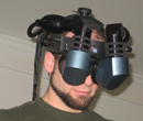
what you don't see in the renders is the head mount, which I salvage from a 20$ welding mask. works like a charm.
and the final build....


went with the "eye of RA" egyptian theme on this one...

here's a picture showing the different lens plates, to swap plates you just loosen the four screws on the front and pop on the new lenses, easy..

this is the custom breakout board that makes it easy to send all data through hdmi, soldering 19 small wires sucks especially when
have to do it for both ends... this helps quite a lot, I'll post the gerber files of this as well. You can use a service such as itead studio, or batch pcb to get cheap
pcbs made.

MODIFIED "LEEP ON THE CHEAP"
I decided I liked the "leep" optics the best, what I needed to do though was grind down parts of the lens edges so the optics would fit properly with the
nose cutout and keep the space between lenses proper for the lcd width, I have made 3d printed holders that the large lenses fit into and allow you to grind down exactly what is needed for a perfect fit, takes about 5 min and turns out perfect.
well there ya go, for now... I still have lots of stuff to improve upon, unfortunately there is never enough time in the day! my current plan looks like the following.
1. setup a proper build log, I'm printing out a 2nd unit as I write this, going to properly document all steps involved now, I did a half ass job while building the first
one, since you try different things and I always forget to just even snap a simple picture along the way... and printing is the slow part, takes about 40 hours of printing per all parts needed...
2. finish design tweeks!, few things I want to add...
a. eye cups to block out exterior light... thinking of making a printed mold, then using prostetic grade silicone to cast a nice single piece that would block out all light.
b. mount for the ps3 move controller, (yup it's going to look silly as hell, but who cares..)
3. develop better tracking integration, I am going to most likely test out a version that uses the ps3 move controller, I've built a virtual camera setup in the past using the ps3 move so it's familiar, I also have it able to track about a 20'x20' volume as I really want position tracking as well as rotation tracking.
If anyone has any feedback, ideas, suggestions, questions, etc... feel free to ask, I'm going to try to help out as much as I can if anyone has issues with their build, now that I've gone though the process of building my own DIY rig.
here is a link to my current BOM, going to keep it updated but it's pretty much complete. >> BOM<<
and if anyone is interested in the pinout configuration on the LCD Controller and HDMI cable, the above schematic and >> this<< document should help you out.
Must say really cool bunch of folks here, thanks for sharing all your knowledge, hopefully I can add to the brain pool.
I'm an fov junkie, I've had other vr hmd's all with complete crap 20-40 deg fov, nothing immersive ever, such a turn off for vr.. when oculus came about It really got me excited about vr again. Thanks Palmer!
ok enough talk, to the build!
I gave myself a few goals to hit for my build.
1. I wanted to make a design that was completely 3d printable on my ultimaker. The benefit I see from 3d printing is you have control of in-fill on the print, this allows you to make a object that is almost completely hollow yet structurally rigid, drastically reducing weight.
2. I wanted to have interchangable lens configurations, with all the posts about different optics, and me not being an optical expert, I wanted to be able to
easily experiment and swap out "lens plates"
3. did not want to have all the electronics strapped to my face, so made my own LVDS, USB, POWER --> HDMI breakout boards to make it easy to send all the
signals through HDMI without any soldering.
4. 120+ deg fov
Glad to say I have hit all the goals, my design is not completely finished there are a few things I want to tweek, add, change.. etc, but I figured this is a
good spot to share it with the community and get some feedback. I am going to post all my files in the next day or two on thingiverse if anyone wants to download and make their own.
I have made 3 interchangable lens plates, for testing of cheap 5x magnifer lenses, the recomended 50mm lenses, and my own variant of "leep on the cheap" (more on that a little later) I'm not quite sure how to accuratly measure fov, but from my estimate is the 50mm lenses give about 90+ deg fov, the cheap magnifiers were terrible, not sure but I quickly dropped them from the design... finally my modified leep design, gives 120+ deg, seems like a lot more actually, but I'm not positive I will post a video that compares the 3 perhaps somone can give me some idea on what I'm seeing fov wise..
I am currently using the hillcrest tracker, can't really say I'm sold on it other than it's tiny!, the mouse emulation mode is not great at all, but I'll reserve judgement untill I have some time to use their sdk and build my own app that directly talks to the tracker.
how about some pictures?
here's the final-ish design I came up with, I really wanted something a bit more organic but had to compromise a bit to make it 3d printer friendly and fit the build volume of the ultimaker.
what you don't see in the renders is the head mount, which I salvage from a 20$ welding mask. works like a charm.
and the final build....
went with the "eye of RA" egyptian theme on this one...
here's a picture showing the different lens plates, to swap plates you just loosen the four screws on the front and pop on the new lenses, easy..
this is the custom breakout board that makes it easy to send all data through hdmi, soldering 19 small wires sucks especially when
have to do it for both ends... this helps quite a lot, I'll post the gerber files of this as well. You can use a service such as itead studio, or batch pcb to get cheap
pcbs made.
MODIFIED "LEEP ON THE CHEAP"
I decided I liked the "leep" optics the best, what I needed to do though was grind down parts of the lens edges so the optics would fit properly with the
nose cutout and keep the space between lenses proper for the lcd width, I have made 3d printed holders that the large lenses fit into and allow you to grind down exactly what is needed for a perfect fit, takes about 5 min and turns out perfect.
well there ya go, for now... I still have lots of stuff to improve upon, unfortunately there is never enough time in the day! my current plan looks like the following.
1. setup a proper build log, I'm printing out a 2nd unit as I write this, going to properly document all steps involved now, I did a half ass job while building the first
one, since you try different things and I always forget to just even snap a simple picture along the way... and printing is the slow part, takes about 40 hours of printing per all parts needed...
2. finish design tweeks!, few things I want to add...
a. eye cups to block out exterior light... thinking of making a printed mold, then using prostetic grade silicone to cast a nice single piece that would block out all light.
b. mount for the ps3 move controller, (yup it's going to look silly as hell, but who cares..)
3. develop better tracking integration, I am going to most likely test out a version that uses the ps3 move controller, I've built a virtual camera setup in the past using the ps3 move so it's familiar, I also have it able to track about a 20'x20' volume as I really want position tracking as well as rotation tracking.
If anyone has any feedback, ideas, suggestions, questions, etc... feel free to ask, I'm going to try to help out as much as I can if anyone has issues with their build, now that I've gone though the process of building my own DIY rig.
here is a link to my current BOM, going to keep it updated but it's pretty much complete. >> BOM<<
and if anyone is interested in the pinout configuration on the LCD Controller and HDMI cable, the above schematic and >> this<< document should help you out.
-
PatimPatam

- Binocular Vision CONFIRMED!
- Posts: 214
- Joined: Thu Jun 28, 2012 1:31 pm
- Location: Barcelona
Re: DIY Oculus Rift - schematics, instructions and build pic
WOW!! That is what i call a WICKED first post! Welcome to the forums!!
-
zoost
- One Eyed Hopeful
- Posts: 29
- Joined: Fri Jun 08, 2012 5:41 am
Re: DIY Oculus Rift - schematics, instructions and build pic
Hi WickedAndy, Very Impressive! I like your design, very practical and elegant. I just have one question. I assume you will use it for gaming. How is the VR experience with your kit?
-
MrGreen

- Diamond Eyed Freakazoid!
- Posts: 741
- Joined: Mon Sep 03, 2012 1:36 pm
- Location: QC, Canada
Re: DIY Oculus Rift - schematics, instructions and build pic
Holy mother of %$&*!

-
space123321
- Binocular Vision CONFIRMED!
- Posts: 236
- Joined: Wed Sep 30, 2009 8:29 pm
Re: DIY Oculus Rift - schematics, instructions and build pic
Outstanding work!
-
brantlew

- Petrif-Eyed
- Posts: 2221
- Joined: Sat Sep 17, 2011 9:23 pm
- Location: Menlo Park, CA
Re: DIY Oculus Rift - schematics, instructions and build pic
@WickedAndy: Nice work! Are you able to find enough content that can handle 120 FOV? Are you doing pre-warp right now or is that down-the-road?
I think the Sparkfun is a better choice than the Hillcrest tracker. But if you're going to go for the full positional tracker then the Move is probably a good option.
I think the Sparkfun is a better choice than the Hillcrest tracker. But if you're going to go for the full positional tracker then the Move is probably a good option.
-
Yoder808
- One Eyed Hopeful
- Posts: 47
- Joined: Sat Sep 08, 2012 2:06 am
Re: DIY Oculus Rift - schematics, instructions and build pic
WickedAndy, that looks amazing!  I wish I had access to a 3D Printer...
-
zacherynuk
- Binocular Vision CONFIRMED!
- Posts: 296
- Joined: Sun Oct 03, 2010 2:56 pm
- Location: England
Re: DIY Oculus Rift - schematics, instructions and build pic
@WickedAndy: Legendary Skills. 
Did you find nice plastics for your dual lens LEEP optics ?
Did you find nice plastics for your dual lens LEEP optics ?
-
OzOnE2k10
- Sharp Eyed Eagle!
- Posts: 436
- Joined: Wed Jan 13, 2010 7:12 am
- Location: UK
Re: DIY Oculus Rift - schematics, instructions and build pic
Damn, I knew I should have searched before I posted my "LVDS via HDMI" guide. lol
Awesome first post! Very nice build
@WickedAndy - It looks like the breakout board fits straight onto the controller's standard 30-pin header (only 16 pins needed), that's perfect!
Does the breakout board point "inwards" inside the controller box?
EDIT: Oh, I see now - the HDMI port points out of the controller box ofc. Does that mean there needs to be a gap between the controller board and the edge of the box?
This will be SO much easier than having to solder both ends, and negates the need for re-using the controller plug too.
Soldering the panel end isn't too bad after the controller is sorted.
btw, did you notice any issues with "sparklies" on the panel image at all?
I'm assuming VDD on the HDMI socket is the backlight +5V supply?
Do you just tie the PWM / Backlight Enable signals to LCD+ at the panel end?
(almost the same pinout as I used. )
I would definitely consider getting some of these made if anyone in the UK / Europe needs a cable soldered.
Many PCB manufactures I find are quite expensive (~£60 just for one "panel"), works out OK in bulk for small boards though.
Thanks, Andy.
OzOnE.
Awesome first post! Very nice build
@WickedAndy - It looks like the breakout board fits straight onto the controller's standard 30-pin header (only 16 pins needed), that's perfect!
Does the breakout board point "inwards" inside the controller box?
EDIT: Oh, I see now - the HDMI port points out of the controller box ofc. Does that mean there needs to be a gap between the controller board and the edge of the box?
This will be SO much easier than having to solder both ends, and negates the need for re-using the controller plug too.
Soldering the panel end isn't too bad after the controller is sorted.
btw, did you notice any issues with "sparklies" on the panel image at all?
I'm assuming VDD on the HDMI socket is the backlight +5V supply?
Do you just tie the PWM / Backlight Enable signals to LCD+ at the panel end?
(almost the same pinout as I used.
I would definitely consider getting some of these made if anyone in the UK / Europe needs a cable soldered.
Many PCB manufactures I find are quite expensive (~£60 just for one "panel"), works out OK in bulk for small boards though.
Thanks, Andy.
OzOnE.
-
OzOnE2k10
- Sharp Eyed Eagle!
- Posts: 436
- Joined: Wed Jan 13, 2010 7:12 am
- Location: UK
Re: DIY Oculus Rift - schematics, instructions and build pic
Hey, Zach!
You'll be pleased to know that I've nearly finished the second cable.
I'll have it wrapped up and soldered tomorrow. Hopefully the wires won't fall off.
You'll be pleased to know that I've nearly finished the second cable.
I'll have it wrapped up and soldered tomorrow. Hopefully the wires won't fall off.
-
Yoder808
- One Eyed Hopeful
- Posts: 47
- Joined: Sat Sep 08, 2012 2:06 am
Re: DIY Oculus Rift - schematics, instructions and build pic
Are you looking at selling these cables (or breakout boards) at some point? (Either you or WickedAny)OzOnE2k10 wrote:Hey, Zach!
You'll be pleased to know that I've nearly finished the second cable.
I'll have it wrapped up and soldered tomorrow. Hopefully the wires won't fall off.
-
OzOnE2k10
- Sharp Eyed Eagle!
- Posts: 436
- Joined: Wed Jan 13, 2010 7:12 am
- Location: UK
Re: DIY Oculus Rift - schematics, instructions and build pic
I might think about soldering some cables, but only with a breakout board...
tbh, this second cable has been a proper PITA for various reasons. The USB connection wouldn't work at first, so I had to wait for more USB cables.
Then I managed to screw up the pinout because I didn't label the wires, and then waited for the foil tape to arrive because I wanted to make it sparkly-free.
With a breakout like Andy has made, it wouldn't be such a pain to solder. Only the panel wires would need to be soldered to one of the breakouts.
It depends how cheaply we / I can get PCBs made. I would imagine it wouldn't be worth it unless I shipped only to the UK / Europe too.
If someone in the US and other Countries wouldn't mind getting a batch of PCBs made and doing some soldering, I think it would help a lot of people out.
I'll have a quick look for some cheaper board houses. I can't promise anything though.
OzOnE.
-
zacherynuk
- Binocular Vision CONFIRMED!
- Posts: 296
- Joined: Sun Oct 03, 2010 2:56 pm
- Location: England
Re: DIY Oculus Rift - schematics, instructions and build pic
WonderfulOzOnE2k10 wrote:Hey, Zach!
You'll be pleased to know that I've nearly finished the second cable.
I'll have it wrapped up and soldered tomorrow. Hopefully the wires won't fall off.
-
Dycus
- Binocular Vision CONFIRMED!
- Posts: 322
- Joined: Wed Aug 15, 2012 1:38 pm
- Contact:
Re: DIY Oculus Rift - schematics, instructions and build pic
Wow, that's one sexy head mount, Andy! Is it light? It looks a bit on the heavy side.
-
rfurlan

- Cross Eyed!
- Posts: 149
- Joined: Wed Jun 20, 2012 1:49 am
- Contact:
Re: DIY Oculus Rift - schematics, instructions and build pic
Whoa, sexy indeed, welcome to the community WickedAndy!
Rod Furlan - bitcortex.com
"The first ultra-intelligent machine is the last invention that man need ever make."
"The first ultra-intelligent machine is the last invention that man need ever make."
-
TheLostBrain
- Cross Eyed!
- Posts: 100
- Joined: Wed Feb 06, 2008 9:10 pm
- Contact:
Re: DIY Oculus Rift - schematics, instructions and build pic
@WickedAndy: Holy shite! . That is bad ass bro!
I'm stuck in my iPhone right now and will check out your post in more detail when I get home... But damn good job!
Btw I've got an ultimaker too and have yet to actually use it for anything (been doing all mine cnc wood) but now I'm definitely inspired to have a go at it.
Also what are you using for design (I'm a solidworks guy at this point)?
Awesome job again!
My Current VR Setup
- N-Vision Datavisor 80 HMD (1280x1024, 80 FOV at 100% Overlap)
- Ascension Technology Flock of Birds 6DOF Magnetic Tracking + Extended Range Transmitter
- Prototype HMD (~100 FOV) - Specs and design to be shared after patent issued.
- IZ3D for non stereo-ready apps
- GlovePie for TrackIR emulation for apps without native Ascension Tech FOB Support
http://www.thelostbrain.com/?tag=/head+mounted+display" onclick="window.open(this.href);return false;
-
MSat
- Golden Eyed Wiseman! (or woman!)
- Posts: 1329
- Joined: Fri Jun 08, 2012 8:18 pm
Re: DIY Oculus Rift - schematics, instructions and build pic
-
WickedAndy
- One Eyed Hopeful
- Posts: 5
- Joined: Thu Aug 30, 2012 1:24 pm
Re: DIY Oculus Rift - schematics, instructions and build pic
Thanks for all the kind comments!, this is really a really fun project....
first let me answer some questions:
I had trying out a 80k-$ vr unit at siggraph this year, it had position tracking, the demo was crude, basically you had to
walk a plank up like 200 feet off the ground, then jump off.. because of the immersion even with cheesy graphics your body
was actually afraid to step off the platform, pretty trippy... If I can get it to that level I'll be happy.. another use is I plan on making
a panoramic 3d viewer app that shows images from the mars lander, and possibly demo it at some schools for kids to learn a bit.
but as of this moment untill I get the tracking done think the VR experience is ok, definately have the fov covered for sure.. now is
time for some content.
take full advantage of it. right now I've been using the "Stereoscopic Fisheye Rendering Techdemo" from another thread on this board, as well as
"Biclops - Open RIFT-Compatibility layer", been playing a bit of mirrors edge with that one, really fun!
I'm going to go ahead and get the sparkfun tracker probably next week, It does appear way more stable in the videos I have seen, and yea
the move is pretty amazing on how accurate it can be.
yup the breakout board just plugs into the header, with a matching board in the hmd, that the lcd cable just plugs into. you just
have to attach the LCD power and your USB connection to the other headers and your good to go. there are 0 sparklies, completely solid
image, right now the VDD from the panel is running thru the hotplug detect pin, and the logic vdd is using the hdmi vdd, I haven't had any issues so far. as for the pwm/backlight doesn't look like my 7-1 board I got from ebay even had those connected, just the power and ground.. I think I'm
going to investigate this a bit further soon. (also look below there is a picture of the breakout board attached inside the case)
is enough interest I'll send out a bigger batch perhaps, PM me if anyone is interested.
optics in a little bit.
btw your wood design case looks pretty cool. I need to get a larger cnc, I have a small 4"x6" (mill volume) sherline cnc, thinking of upgrading soon
to one of those 24"x36" router tables from china.
I am currently uploading all the files for 3d printing to thingiverse now, I'll make another post once everything is there and ready!
here's a few more pictures, and a video that trys to show the extent of the fov in the display.
Inside view of controller box, showing the lvds - hdmi breakout board.

here's how it looks when being 3d printed before being cleaned up.

and a view without the lenses on showing the LCD only.

and the video peering into the lens, playing mirrors edge.
http://youtu.be/p10V3lca-DY
[youtube]http://youtu.be/p10V3lca-DY[/youtube]
another video showing the hmd in use...
http://youtu.be/pujeMSP6dmo
[youtube]http://youtu.be/pujeMSP6dmo[/youtube]
- andy
andy
first let me answer some questions:
I actually have a few uses in mind, gaming for sure, but also one of my other goals was to replicate the experiencezoost: I assume you will use it for gaming. How is the VR experience with your kit
I had trying out a 80k-$ vr unit at siggraph this year, it had position tracking, the demo was crude, basically you had to
walk a plank up like 200 feet off the ground, then jump off.. because of the immersion even with cheesy graphics your body
was actually afraid to step off the platform, pretty trippy... If I can get it to that level I'll be happy.. another use is I plan on making
a panoramic 3d viewer app that shows images from the mars lander, and possibly demo it at some schools for kids to learn a bit.
but as of this moment untill I get the tracking done think the VR experience is ok, definately have the fov covered for sure.. now is
time for some content.
yeah that's one issue, you really sort of crop into the image with high fov, and the content I think needs to be bit more specificly crafted tobrantlew: Nice work! Are you able to find enough content that can handle 120 FOV? Are you doing pre-warp right now or is that down-the-road? I think the Sparkfun is a better choice than the Hillcrest tracker. But if you're going to go for the full positional tracker then the Move is probably a good option.
take full advantage of it. right now I've been using the "Stereoscopic Fisheye Rendering Techdemo" from another thread on this board, as well as
"Biclops - Open RIFT-Compatibility layer", been playing a bit of mirrors edge with that one, really fun!
I'm going to go ahead and get the sparkfun tracker probably next week, It does appear way more stable in the videos I have seen, and yea
the move is pretty amazing on how accurate it can be.
I've just been using glass lenses for now, but I actually might make a mold of them and try casting some of my own with optically clear acrylic.zacherynuk: Did you find nice plastics for your dual lens LEEP optics ?
Ozone2k10: nice writeup on the lvds - hdmi btw!Ozone2k10: It looks like the breakout board fits straight onto the controller's standard 30-pin header (only 16 pins needed), that's perfect!
Does the breakout board point "inwards" inside the controller box?
EDIT: Oh, I see now - the HDMI port points out of the controller box ofc. Does that mean there needs to be a gap between the controller board and the edge of the box?
This will be SO much easier than having to solder both ends, and negates the need for re-using the controller plug too.
Soldering the panel end isn't too bad after the controller is sorted.
btw, did you notice any issues with "sparklies" on the panel image at all?
I'm assuming VDD on the HDMI socket is the backlight +5V supply?
Do you just tie the PWM / Backlight Enable signals to LCD+ at the panel end?
yup the breakout board just plugs into the header, with a matching board in the hmd, that the lcd cable just plugs into. you just
have to attach the LCD power and your USB connection to the other headers and your good to go. there are 0 sparklies, completely solid
image, right now the VDD from the panel is running thru the hotplug detect pin, and the logic vdd is using the hdmi vdd, I haven't had any issues so far. as for the pwm/backlight doesn't look like my 7-1 board I got from ebay even had those connected, just the power and ground.. I think I'm
going to investigate this a bit further soon. (also look below there is a picture of the breakout board attached inside the case)
wasn't really planning on it, but I actully have a batch of them coming though, 10 boards, next week, would of been sooner but china's national holiday is slowing things down a bit.. the pcb prices are pretty good from itead studio in china, 9$ for the pcb, and 27$ for shipping (you can go cheap on the shipping but it takes forever!) not bad for prototyping, concidering in the US all board houses would take an arm and leg. if thereYoder808: Are you looking at selling these cables (or breakout boards) at some point?
is enough interest I'll send out a bigger batch perhaps, PM me if anyone is interested.
Thanks dycus! yeah it's actually pretty light, I just weighed it.... 1 lb - 8 oz with the glass leep optics. I'll get another weight for the otherDycus: Wow, that's one sexy head mount, Andy! Is it light? It looks a bit on the heavy side.
optics in a little bit.
yup I to am a solidworks guy, really makes designing fun.Also what are you using for design (I'm a solidworks guy at this point)?
btw your wood design case looks pretty cool. I need to get a larger cnc, I have a small 4"x6" (mill volume) sherline cnc, thinking of upgrading soon
to one of those 24"x36" router tables from china.
I do notice the difference but not all that much, once you tighten down the headband it pretty much floats in front of you, the leep configuration weight is 1lb 8oz, and I'll weigh the other configuration soon.MSat: Very sweet build! The interchangeable optics are too cool. How noticeable is the added weight when using Leep?
I am currently uploading all the files for 3d printing to thingiverse now, I'll make another post once everything is there and ready!
here's a few more pictures, and a video that trys to show the extent of the fov in the display.
Inside view of controller box, showing the lvds - hdmi breakout board.
here's how it looks when being 3d printed before being cleaned up.
and a view without the lenses on showing the LCD only.
and the video peering into the lens, playing mirrors edge.
http://youtu.be/p10V3lca-DY
[youtube]http://youtu.be/p10V3lca-DY[/youtube]
another video showing the hmd in use...
http://youtu.be/pujeMSP6dmo
[youtube]http://youtu.be/pujeMSP6dmo[/youtube]
-
-
brantlew
- Petrif-Eyed
- Posts: 2221
- Joined: Sat Sep 17, 2011 9:23 pm
- Location: Menlo Park, CA
Re: DIY Oculus Rift - schematics, instructions and build pic
Cool.
That's a mean helmet. How the hell did you get your girlfriend to wear that thing? My wife just laughs at me when I'm suited up.
That's a mean helmet. How the hell did you get your girlfriend to wear that thing? My wife just laughs at me when I'm suited up.
-
WickedAndy
- One Eyed Hopeful
- Posts: 5
- Joined: Thu Aug 30, 2012 1:24 pm
Re: DIY Oculus Rift - schematics, instructions and build pic
as promised here are the files! come and get em!
http://www.thingiverse.com/thing:31758
fyi, I'll be offline for the next 2 days or so, on a trip... will be shooting some stereo gopro footage to hopefully be able to run
on the helmet
-
-
WickedAndy
- One Eyed Hopeful
- Posts: 5
- Joined: Thu Aug 30, 2012 1:24 pm
Re: DIY Oculus Rift - schematics, instructions and build pic
just a few more pics too...
this is how the lenses are ground down, left picture is before sanding, and right picture is after, the printed jig makes it a snap!

and the finished lenses

this is how the lenses are ground down, left picture is before sanding, and right picture is after, the printed jig makes it a snap!
and the finished lenses
-
brantlew
- Petrif-Eyed
- Posts: 2221
- Joined: Sat Sep 17, 2011 9:23 pm
- Location: Menlo Park, CA
Re: DIY Oculus Rift - schematics, instructions and build pic
Nice. You're pretty handy with that printer.
-
blazespinnaker

- Certif-Eyed!
- Posts: 541
- Joined: Sat Sep 01, 2012 11:53 pm
Re: DIY Oculus Rift - schematics, instructions and build pic
Amazing work. We live in incredible times.brantlew wrote:Nice. You're pretty handy with that printer.
One small comment though .. I noticed the HMD stretches out a fair distance from the head. The 3d printer optimized infill is great for weight but do you have any concerns about lever effects? One of the things that I think will be good about oculus (if they're similar to their pictures), is that they try to push it all up against your face so not as much stress on your neck.
Last edited by blazespinnaker on Fri Oct 05, 2012 2:11 pm, edited 1 time in total.
Gear VR: Maybe OVR isn't so evil after all!
-
OzOnE2k10
- Sharp Eyed Eagle!
- Posts: 436
- Joined: Wed Jan 13, 2010 7:12 am
- Location: UK
Re: DIY Oculus Rift - schematics, instructions and build pic
Duh, I'm feeling very silly today. Of course, the original LVDS cable plugs directly into the breakout board. lolWickedAndy: yup the breakout board just plugs into the header, with a matching board in the hmd
That's great - no tricky soldering to do at all then, just the pin headers and a few USB / backlight wires (easy).
Thanks, Andy. I've just pinched your gerbers (ooh err, misses).
OzOnE.
EDIT: Ahh, I think I see now. You might find that your LCD- / LCD+ wires are actually the backlight supply and the BLON signal. (as opposed to backlight supply + Ground).
If you get chance, could you possibly test the voltage on the controller between ground and the Red wire from the 6-pin plug?
When I had Zach's panel, the backlight worked from +5V. I'm wondering if yours is connected to +12V instead?
-
Fredz
- Petrif-Eyed
- Posts: 2255
- Joined: Sat Jan 09, 2010 2:06 pm
- Location: Perpignan, France
- Contact:
Re: DIY Oculus Rift - schematics, instructions and build pic
Really nice job on this DIY HMD, congrats !
How are your GoPro connected ? Using the stock 3D HERO System and its limited interaxial or did you modify it to have an higher interaxial ?WickedAndy wrote:fyi, I'll be offline for the next 2 days or so, on a trip... will be shooting some stereo gopro footage to hopefully be able to run on the helmet
Last edited by Fredz on Fri Oct 05, 2012 3:41 pm, edited 1 time in total.
-
Dycus
- Binocular Vision CONFIRMED!
- Posts: 322
- Joined: Wed Aug 15, 2012 1:38 pm
- Contact:
Re: DIY Oculus Rift - schematics, instructions and build pic
The backlight + wire is usually connected straight to the barrel plug, not even through the fuse. It'll get whatever voltage you give the driver board. I've run them from 13.5v down to 4.5v and they all work fine. The other wire is a PWM signal for backlight brightness, and can range from 3v to 5v (usually).OzOnE2k10 wrote:Ahh, I think I see now. You might find that your LCD- / LCD+ wires are actually the backlight supply and the BLON signal. (as opposed to backlight supply + Ground).
If you get chance, could you possibly test the voltage on the controller between ground and the Red wire from the 6-pin plug?
When I had Zach's panel, the backlight worked from +5V. I'm wondering if yours is connected to +12V instead?