DIY Oculus Rift - schematics, instructions and build pics!

Post Reply
CharlesK
One Eyed Hopeful
Posts: 9
Joined: Sat Jul 13, 2013 5:59 am

Re: DIY Oculus Rift - schematics, instructions and build pic

Post by CharlesK »

Hannibalj2 wrote:Hey that looks pretty neat!!! :mrgreen:

Is the sensor the GY-85, or 86? How does it perform? I just got the nano arduino v3. Maybe you can get that one and drop some of weigh off your unit.

What software is it compatible with?

I'm having problems with my Yei 3space Sensor at the moment.

I am updating the built of my unit here:
http://www.mtbs3d.com/phpBB/viewtopic.php?f=26&t=18335

Looking good mate!! :D
Thanks! it's a gy-85 running on existing ahrs code i found online. calibrated it and run it through freepie. freepie can emulate track ir and work with vireio. i used the uno since it's what i had. now i've got a working prototype i might try and scale it all down to look neat. tracking feels perfect.

JustJoshin wrote:Great job Charles!

What resolution/panel did you choose?

Btw, it might not look like much but there is a certain level of personal satisfaction that comes with a DIY job so nice work!
Here's the panel i got. http://www.ebay.com/itm/121140604583?ss ... 1497.l2649 didn't have to pay tax either :D. That seller also sells the same panel with vga only, it has a very small driver compared to the one i got.


Having slight issues getting the image to feel right. my eyes feel slightly crossed because the center of the images are too far inwards. how do i change the image separation in vireio? pressing f2 helps but it stops right before where it needs to be (in half life 2 that is, dirt 2 windowed mode works fine). I tried DIY rift mode, rift mode and side by side mode.
marinjonkman
One Eyed Hopeful
Posts: 3
Joined: Mon Feb 13, 2012 7:57 am

Re: DIY Oculus Rift - schematics, instructions and build pic

Post by marinjonkman »

Curious if this will arrive as described:

Firefly V65
6.45 Inch 1080*1920 8-)
IPS

http://www.aliexpress.com/item/MTK6589T ... 00887.html
http://www.youtube.com/watch?v=ECM3rlA3748
thirty3baboons
One Eyed Hopeful
Posts: 42
Joined: Sat Sep 01, 2012 11:00 am

Re: DIY Oculus Rift - schematics, instructions and build pic

Post by thirty3baboons »

Been having a bit of a play myself.

ImageImageImage
ImageImage

built for my iphone5, but easy enough to adapt. This version is nearly there. just need to tweak a few things. Demo is a quick recreation of bioshock's opening scene I knocked up in unity with prefabs for the camera setup, motion tracking and lens distortion. Has the advantage of being (1) Cheap, (2) small, (3) retina rez, (4) wireless (even with headphones you're untethered)

fun making it and now fun tweaking it.

All in, $60 (+ the iphone I already had) and most of that's the 3D print cost (I am extremely tempted to buy a 3D printer now!)

I posted another thread, so I won't harp on here.

http://www.mtbs3d.com/phpBB/viewtopic.php?f=138&t=18441
mcdohl
One Eyed Hopeful
Posts: 8
Joined: Tue Jul 16, 2013 10:57 am

Re: DIY Oculus Rift - schematics, instructions and build pic

Post by mcdohl »

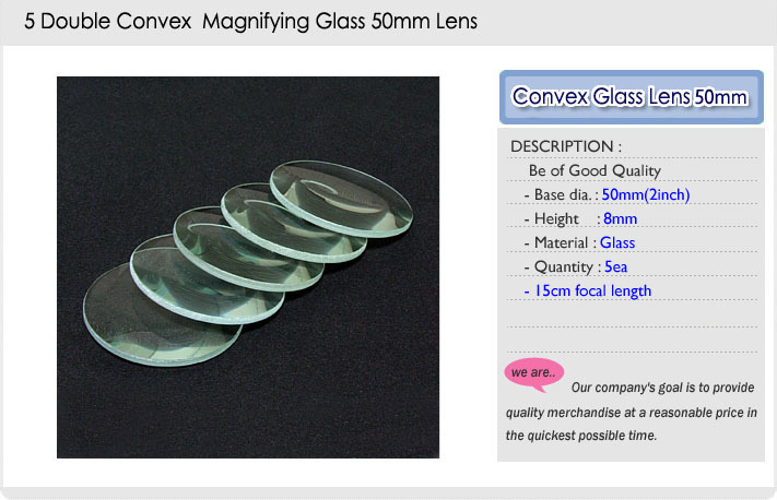
hello everyone, I've already done a hmd with a tablet 7 " and the lenses of a visor 3d Olga. But I'm not happy with the size of these lenses, is a little small, about 3 centimeter.'ve found on Ebay these lenses, you did not think you could use them for a 7 "display? The price is really interesting.
Image
3dvison
Diamond Eyed Freakazoid!
Posts: 718
Joined: Sun Oct 24, 2010 7:25 pm

Re: DIY Oculus Rift - schematics, instructions and build pic

Post by 3dvison »

Has anyone ever found a place to buy the exact same lenses used in the Dev.Kit.Rift ?
CharlesK
One Eyed Hopeful
Posts: 9
Joined: Sat Jul 13, 2013 5:59 am

Re: DIY Oculus Rift - schematics, instructions and build pic

Post by CharlesK »

I've tried playing games with native rift support and vireio on my diy rift. my rift uses a 5.6 inch screen. now, i might be wrong but the screen separation (ipd? or is that only lens separation?) becomes less on a smaller screen. this means my eyes have to go slightly cross eyed to view one image. is there a way to separate images to match the same separation as on a 7 inch screen?

Best experience so far has been outerra. all setting are editable including screen separation. I didn't get the same level of immersion in any other game.

If anyone wants my mouse emulation code for freepie to run with outerra i'll post it.

EDIT: another option would be to "zoom in" on the monitor. that way the image would be enlarged thus creating the same effect. (maybe :? )
baljagat
One Eyed Hopeful
Posts: 2
Joined: Fri Aug 16, 2013 7:23 am

Re: DIY Oculus Rift - schematics, instructions and build pic

Post by baljagat »

Hi all, I am new here. Quite interesting thread. May be we can use car headlight reflector as a separator between lens and LCD ,

Image
though we have to work a bit for measurements, probably plastic ones :)
chrisjarram
Binocular Vision CONFIRMED!
Posts: 304
Joined: Sat Dec 22, 2007 3:38 am

Re: DIY Oculus Rift - schematics, instructions and build pic

Post by chrisjarram »

As exciting as this is 1080p simply won't cut it, you'll get it, think it's better than 1280x800 yes, and then instantly yearn for more - ideally we need 4k per eye to be at the limits of where we want to be. Anything is an improvement sure, but I think the commercial Rift will more likely use a screen around the 2560 * 1440 AMOLED (tiny switching time) mark, as small (7") screens of this spec are coming in the next 12 months or so in tablet devices. That's where things will get more interesting, I can't wait :o)
XFX GTX 280 XXX,BFG 7900GTX,Q6600,4gbXMS2,3TB RAID,2xWD Raptors,MountainMods U2-UFO Case,1KW Thermaltake PSU, 3x BenQ MP720p,Full active sim setup inc actuators,shakers,wind,THX sound.CrystalEyes 3,6 wireless ED w/ hipower emitter.
marinjonkman
One Eyed Hopeful
Posts: 3
Joined: Mon Feb 13, 2012 7:57 am

Re: DIY Oculus Rift - schematics, instructions and build pic

Post by marinjonkman »

chrisjarram wrote:As exciting as this is 1080p simply won't cut it, you'll get it, think it's better than 1280x800 yes, and then instantly yearn for more - ideally we need 4k per eye to be at the limits of where we want to be. Anything is an improvement sure, but I think the commercial Rift will more likely use a screen around the 2560 * 1440 AMOLED (tiny switching time) mark, as small (7") screens of this spec are coming in the next 12 months or so in tablet devices. That's where things will get more interesting, I can't wait :o)

Well that depends what your looking for. Of course creating "virtual reality" means go high on the resolution. However, if you want to go portable on the short term, rendering is unfortunately an issue. Don't underestimate the 2K x 2 stereo x 1.7 prewarp render loop. And by looking at a 1080P screen through the lenses, it is quite an improvement compared to the current set-up.
jexnerRW
One Eyed Hopeful
Posts: 1
Joined: Tue Aug 13, 2013 2:46 pm

Re: DIY Oculus Rift - schematics, instructions and build pic

Post by jexnerRW »

Does anyone have contact information for the guy designing the HDMI to MIPI board?
Peva3
One Eyed Hopeful
Posts: 29
Joined: Tue Aug 06, 2013 7:27 am

Re: DIY Oculus Rift - schematics, instructions and build pic

Post by Peva3 »

jexnerRW wrote:Does anyone have contact information for the guy designing the HDMI to MIPI board?
Who, LaserEdge?

http://www.mtbs3d.com/phpBB/viewtopic.p ... 80#p141532
OzOnE2k10
Sharp Eyed Eagle!
Posts: 436
Joined: Wed Jan 13, 2010 7:12 am
Location: UK

Re: DIY Oculus Rift - schematics, instructions and build pic

Post by OzOnE2k10 »

Wow, I didn't know about that project.

I don't think LaserEdge is Daniel, but either way it's fantastic news to be seeing more MIPI adapters being developed.

Daniel is still working on his design too. He has a few different panels for testing now.
His e-mail address is on his site...
http://dp2retina.rozsnyo.com/

OzOnE.
Peva3
One Eyed Hopeful
Posts: 29
Joined: Tue Aug 06, 2013 7:27 am

Re: DIY Oculus Rift - schematics, instructions and build pic

Post by Peva3 »

OzOnE2k10 wrote:Wow, I didn't know about that project.

I don't think LaserEdge is Daniel, but either way it's fantastic news to be seeing more MIPI adapters being developed.

Daniel is still working on his design too. He has a few different panels for testing now.
His e-mail address is on his site...
http://dp2retina.rozsnyo.com/

OzOnE.
It would be awesome for Daniel and LaserEdge to team up and get a production model going, I think this is going to be a pretty big deal for the whole DIY HMD community going forward.
Inscothen
Binocular Vision CONFIRMED!
Posts: 203
Joined: Fri Aug 31, 2012 11:21 pm

Re: DIY Oculus Rift - schematics, instructions and build pic

Post by Inscothen »

LaserEdge's MIPI solution looks really great. Perfect size. I'm hoping to see it working with the Sharp 5.9" panel soon. If the circuit is under $100, that's a buy for me. :D

Still curious on other solutions being worked on.
studdart
One Eyed Hopeful
Posts: 4
Joined: Tue Aug 13, 2013 5:10 pm

Re: DIY Oculus Rift - schematics, instructions and build pic

Post by studdart »

Wow, things escalate quickly in the LCD world! Just seen this on Engadget:

http://www.engadget.com/2013/08/20/lg-d ... d-display/

That's a 5.5" 2560x1440 screen, 538ppi. Pretty incredible.

edit:Has its own thread already http://www.mtbs3d.com/phpBB/viewtopic.php?f=140&t=18505
CharlesK
One Eyed Hopeful
Posts: 9
Joined: Sat Jul 13, 2013 5:59 am

Re: DIY Oculus Rift - schematics, instructions and build pic

Post by CharlesK »

How do you guys move away the screen driver from the hmd? It's kind of bulky/heavy. is it possible to buy longer lvds cables or can i cut it and make it longer? what's the maximum length i can make it without signal loss? Thanks.

EDIT: just ordered a second lvds cable to do some tests. will update when i know more.
OzOnE2k10
Sharp Eyed Eagle!
Posts: 436
Joined: Wed Jan 13, 2010 7:12 am
Location: UK

Re: DIY Oculus Rift - schematics, instructions and build pic

Post by OzOnE2k10 »

@CharlesK - is that LVDS cable for the original Dev Kit LCD?

You could try extending the dev kit LVDS cable using an HDMI cable (actually, I still need to try that).

Here are the pinouts for the Dev Kit LVDS. The pins are labelled at the LCD end anyway though...
http://www.mtbs3d.com/phpbb/viewtopic.p ... 20#p139496

And if you use the HDMI pairs for the LVDS pairs, it should work OK...
http://www.mtbs3d.com/phpBB/viewtopic.php?f=140&t=15554

With the right choice of pins, it should work to pass USB through the same cable.
Here are the HDMI pins I used for the Hydis panel extension

Pin 13. Backlight ON/OFF + PWM.
Pin 14. USB +5V (Red)
Pin 15. USB Data- (White)
Pin 16. USB Data+ (Green)
Pin 17. GND / (USB Black)
Pin 18. +5V (Backlight Supply)
Pin 19. +3V3 (Panel Supply)


Pins 15 and 16 on HDMI are probably the best bet for USB as they're more likely to be shielded (on a decent cable).

Just make sure not to get the 3V3 and 5V lines mixed up. :o

btw, which type of LVDS cable did you buy / where did you get it from?

EDIT: Just realized you're probably talking about a DIY build. My guide may still be useful to you though. ;)
CharlesK
One Eyed Hopeful
Posts: 9
Joined: Sat Jul 13, 2013 5:59 am

Re: DIY Oculus Rift - schematics, instructions and build pic

Post by CharlesK »

OzOnE2k10 wrote:@CharlesK - is that LVDS cable for the original Dev Kit LCD?

You could try extending the dev kit LVDS cable using an HDMI cable (actually, I still need to try that).

Here are the pinouts for the Dev Kit LVDS. The pins are labelled at the LCD end anyway though...
http://www.mtbs3d.com/phpbb/viewtopic.p ... 20#p139496

And if you use the HDMI pairs for the LVDS pairs, it should work OK...
http://www.mtbs3d.com/phpBB/viewtopic.php?f=140&t=15554

With the right choice of pins, it should work to pass USB through the same cable.
Here are the HDMI pins I used for the Hydis panel extension

Pin 13. Backlight ON/OFF + PWM.
Pin 14. USB +5V (Red)
Pin 15. USB Data- (White)
Pin 16. USB Data+ (Green)
Pin 17. GND / (USB Black)
Pin 18. +5V (Backlight Supply)
Pin 19. +3V3 (Panel Supply)


Pins 15 and 16 on HDMI are probably the best bet for USB as they're more likely to be shielded (on a decent cable).

Just make sure not to get the 3V3 and 5V lines mixed up. :o

btw, which type of LVDS cable did you buy / where did you get it from?

EDIT: Just realized you're probably talking about a DIY build. My guide may still be useful to you though. ;)

It is indeed for a diy rift. All i did was email the seller i bought the screen from and he sold me a separate lvds cable for 16$. this is the screen i have http://www.ebay.com/itm/121140604583?ss ... 1497.l2649. The seller only has one length, he told me he might be able to find me a longer cable but it would cost a lot more and take some time so i'll just attempt it myself.

Thanks for the HDMI cable tip, i still have a broken one laying around. do you think it would be possible to run my sensor wires through it too? that would mean i only have 1 cable running to the hmd. i'll post results as soon as i know more.
OzOnE2k10
Sharp Eyed Eagle!
Posts: 436
Joined: Wed Jan 13, 2010 7:12 am
Location: UK

Re: DIY Oculus Rift - schematics, instructions and build pic

Post by OzOnE2k10 »

oic, looks like a Toshiba panel you have there, with a Realtek / Vitrolight style controller.

What sort of sensors are you using?
Is it a headtracker that works via USB, or something else?

I'd need to see the pinouts or datasheet to see if it's possible to use the same HDMI cable.
There are only a few spare signals in a standard HDMI cable for passing your extra data though.

USB on the dev kit is easy enough ofc, because it's just the two data wires (plus power).
CharlesK
One Eyed Hopeful
Posts: 9
Joined: Sat Jul 13, 2013 5:59 am

Re: DIY Oculus Rift - schematics, instructions and build pic

Post by CharlesK »

OzOnE2k10 wrote:oic, looks like a Toshiba panel you have there, with a Realtek / Vitrolight style controller.

What sort of sensors are you using?
Is it a headtracker that works via USB, or something else?

I'd need to see the pinouts or datasheet to see if it's possible to use the same HDMI cable.
There are only a few spare signals in a standard HDMI cable for passing your extra data though.

USB on the dev kit is easy enough ofc, because it's just the two data wires (plus power).
I'm running a gy-85 sensor using an arduino. i have 4 wires running from the arduino to the sensor. The gy-85 runs great on razor ahrs firmware. On some games i tried using vireio it seems slightly choppy when moving my head. playing outerra seemed a lot smoother tho.
OzOnE2k10
Sharp Eyed Eagle!
Posts: 436
Joined: Wed Jan 13, 2010 7:12 am
Location: UK

Re: DIY Oculus Rift - schematics, instructions and build pic

Post by OzOnE2k10 »

CharlesK wrote:I'm running a gy-85 sensor using an arduino. i have 4 wires running from the arduino to the sensor. The gy-85 runs great on razor ahrs firmware. On some games i tried using vireio it seems slightly choppy when moving my head. playing outerra seemed a lot smoother tho.
Is that four wires total, or four wires not including power?

Which signals are connected to the Arduino (how many wires total)?...

VCC_IN
3V3
GND
SCL
SDA
M_DRDY
A_INT1
G_INT


Might be enough pins to pass through HDMI.
If it's I2C, the data rate will be far lower than USB, so should be fine as long as the cable isn't way too long.

SCL and SDA should ideally go via pins 15 and 16 on the HDMI.

For any interrupt / ready signals on the GY-85, it will depend on how many different voltage supplies your panel needs for logic / backlight.
CharlesK
One Eyed Hopeful
Posts: 9
Joined: Sat Jul 13, 2013 5:59 am

Re: DIY Oculus Rift - schematics, instructions and build pic

Post by CharlesK »

OzOnE2k10 wrote:
CharlesK wrote:I'm running a gy-85 sensor using an arduino. i have 4 wires running from the arduino to the sensor. The gy-85 runs great on razor ahrs firmware. On some games i tried using vireio it seems slightly choppy when moving my head. playing outerra seemed a lot smoother tho.
Is that four wires total, or four wires not including power?

Which signals are connected to the Arduino (how many wires total)?...

VCC_IN
3V3
GND
SCL
SDA
M_DRDY
A_INT1
G_INT


Might be enough pins to pass through HDMI.
If it's I2C, the data rate will be far lower than USB, so should be fine as long as the cable isn't way too long.

SCL and SDA should ideally go via pins 15 and 16 on the HDMI.

For any interrupt / ready signals on the GY-85, it will depend on how many different voltage supplies your panel needs for logic / backlight.
These are the 4 connected to the sensor:
vcc_in
gnd
scl
sda

The lvds cable has 12 pins with one of the pins having 4 (green) wires run to it.

not sure what the difference between I2C and usb is. i have my sensor connected to arduino and the arduino communicates with the pc through usb. when you say usb do you mean the sensor is directly connected to the pc?
OzOnE2k10
Sharp Eyed Eagle!
Posts: 436
Joined: Wed Jan 13, 2010 7:12 am
Location: UK

Re: DIY Oculus Rift - schematics, instructions and build pic

Post by OzOnE2k10 »

CharlesK wrote:These are the 4 connected to the sensor:
vcc_in
gnd
scl
sda

The lvds cable has 12 pins with one of the pins having 4 (green) wires run to it.

not sure what the difference between I2C and usb is. i have my sensor connected to arduino and the arduino communicates with the pc through usb. when you say usb do you mean the sensor is directly connected to the pc?
That's good. Should be fine to extend via an HDMI cable...

GY-85...........HDMI
VCC_IN.........Pin 18
GND.............Pin 17
SCL..............Pin 15
SDA.............Pin 16


The GY-85 has an onboard voltage reg, so it's best to run +5V through to pin 18 to power it.
(Again, very important not to put +5V into the Toshiba panel, as it likely runs on 3.3V!)

Here's the brief datasheet to the NT68676 controller (page 6 shows the LVDS connector pinouts)...
http://www.vslcd.com/Specification/M.NT68676.2A.pdf

The pinouts (at the controller end!) are exactly the same as for the usual Vitrolight / "Realtek" controller.

The Toshiba panel will likely have a different pinout to the 5.6" Hydis panel though, so you'd need to label all the wires at the controller end, then solder each wire to the appropriate pin on some HDMI sockets.

Most of my guide applies to your controller, just ignore the "panel end" diagram and photo...
http://www.mtbs3d.com/phpBB/viewtopic.php?f=140&t=15554

(The Toshiba panel may even have the same pinout as the Hydis, but I can't find a datasheet for the Toshiba atm. Best just to go by the controller end wires instead, and carefully label them individually with tape etc.)

From the eBay photo, it looks like the bunch of red and green wires are actually all +3V3 power for the panel and / or backlight?
Pin 1 on the controller is marked by the small arrow on the PCB (next to the white connector for the keypad).
Pin 2 is then above pin 1, like this...

2-4-6-8-10-12-14-16-18-20-22-24-26-28-30
1-3-5-7-9--11-13-15-17-19-21-23-25-27-29

Hard to tell from the eBay pic, but looks like the black wires are going to pins 13 and 14 (would be the Grounds if they are?).

You should really confirm the voltages and ground wires using a multimeter before going any further.

I found that those HDMI couplers / "twisty" things make things easier for soldering the small wires too.
The LVDS wires are very thin though, so can be a pain to solder.

Instead of snipping the pins off the LVDS wires, you can remove the pins from the connector and solder to those?
Or, the LVDS connector should plug into a standard 2mm pitch header. Can be pricey on eBay, but probably cheaper from an electronics company...

http://www.ebay.co.uk/itm/HEADER-2MM-DU ... 3f273b77c6


At least that way you can preserve the original LVDS connector.

Let me know how you get on. ;)

OzOnE.
CharlesK
One Eyed Hopeful
Posts: 9
Joined: Sat Jul 13, 2013 5:59 am

Re: DIY Oculus Rift - schematics, instructions and build pic

Post by CharlesK »

OzOnE2k10 wrote:
CharlesK wrote:These are the 4 connected to the sensor:
vcc_in
gnd
scl
sda

The lvds cable has 12 pins with one of the pins having 4 (green) wires run to it.

not sure what the difference between I2C and usb is. i have my sensor connected to arduino and the arduino communicates with the pc through usb. when you say usb do you mean the sensor is directly connected to the pc?
That's good. Should be fine to extend via an HDMI cable...

GY-85...........HDMI
VCC_IN.........Pin 18
GND.............Pin 17
SCL..............Pin 15
SDA.............Pin 16


The GY-85 has an onboard voltage reg, so it's best to run +5V through to pin 18 to power it.
(Again, very important not to put +5V into the Toshiba panel, as it likely runs on 3.3V!)

Here's the brief datasheet to the NT68676 controller (page 6 shows the LVDS connector pinouts)...
http://www.vslcd.com/Specification/M.NT68676.2A.pdf

The pinouts (at the controller end!) are exactly the same as for the usual Vitrolight / "Realtek" controller.

The Toshiba panel will likely have a different pinout to the 5.6" Hydis panel though, so you'd need to label all the wires at the controller end, then solder each wire to the appropriate pin on some HDMI sockets.

Most of my guide applies to your controller, just ignore the "panel end" diagram and photo...
http://www.mtbs3d.com/phpBB/viewtopic.php?f=140&t=15554

(The Toshiba panel may even have the same pinout as the Hydis, but I can't find a datasheet for the Toshiba atm. Best just to go by the controller end wires instead, and carefully label them individually with tape etc.)

From the eBay photo, it looks like the bunch of red and green wires are actually all +3V3 power for the panel and / or backlight?
Pin 1 on the controller is marked by the small arrow on the PCB (next to the white connector for the keypad).
Pin 2 is then above pin 1, like this...

2-4-6-8-10-12-14-16-18-20-22-24-26-28-30
1-3-5-7-9--11-13-15-17-19-21-23-25-27-29

Hard to tell from the eBay pic, but looks like the black wires are going to pins 13 and 14 (would be the Grounds if they are?).

You should really confirm the voltages and ground wires using a multimeter before going any further.

I found that those HDMI couplers / "twisty" things make things easier for soldering the small wires too.
The LVDS wires are very thin though, so can be a pain to solder.

Instead of snipping the pins off the LVDS wires, you can remove the pins from the connector and solder to those?
Or, the LVDS connector should plug into a standard 2mm pitch header. Can be pricey on eBay, but probably cheaper from an electronics company...

http://www.ebay.co.uk/itm/HEADER-2MM-DU ... 3f273b77c6


At least that way you can preserve the original LVDS connector.

Let me know how you get on. ;)

OzOnE.
Thanks for the detailed information. as soon as i get my stuff i'll give it a go and post an update.
OzOnE2k10
Sharp Eyed Eagle!
Posts: 436
Joined: Wed Jan 13, 2010 7:12 am
Location: UK

Re: DIY Oculus Rift - schematics, instructions and build pic

Post by OzOnE2k10 »

Hi,

I got a bit bored, so I just typed up some pinouts...
(I never actually posted the LVDS-to-"HDMI" pinouts like this before, so it's handy anyway.)

The LVDS pinouts should be the same on most "Vitrolight" / Realtek / NT68676 controllers,
but you need to double-check the pinout for your particular controller!...


*** Controller LVDS ***.............*** "HDMI" Cable ***
Cont pin 24 (TXE2+)....................Pin 1. LVDS Data2+
Cont pin 25 (GND).......................Pin 2. LVDS Data2 Shield (GND)
Cont pin 23 (TXE2-)....................Pin 3. LVDS Data2–
Cont pin 22 (TXE1+)...................Pin 4. LVDS Data1+
Cont pin 14 (GND)......................Pin 5. LVDS Data1 Shield (GND)
Cont pin 21 (TXE1-)...................Pin 6. LVDS Data1–
Cont pin 20 (TXE0+)...................Pin 7. LVDS Data0+
Cont pin 13 (GND)......................Pin 8. LVDS Data0 Shield (GND)
Cont pin 19 (TXE0-)....................Pin 9. LVDS Data0–
Cont pin 28 (TXEC+)...................Pin 10. LVDS Clock+
Cont pin 26 (GND)......................Pin 11. LVDS Clock Shield (GND)
Cont pin 27 (TXEC-)...................Pin 12. LVDS Clock–
Cont pins 1,2,3 VSEL (3V3)..........Pin 13. VSEL (3V3), Panel power
Cont pins 1,2,3 VSEL (3V3)..........Pin 14. VSEL (3V3), Panel power

Arduino pin A5? (SCL)...............Pin 15. GY-85 SCL
Arduino pin A4? (SDA)...............Pin 16. GY-85 SDA
Arduino GND.............................Pin 17. GY-85 GND
Arduino +5V.............................Pin 18. GY-85 VCC_IN (+5V)

Cont pins 4,5,6 GND.................Pin 19. GND, Panel power Ground.

I'm assuming the GY-85 normally connects directly to the SCL / SDA pins on the Arduino? (pins A5, and A4 respectively on the Duemilanove / Uno / Leonardo ?)

EDIT: Might as well repost this...

Pin 1 on the controller is marked by the small arrow on the PCB (next to the white connector for the keypad).
Pin 2 is then above pin 1, like this...

2-4-6-8-10-12-14-16-18-20-22-24-26-28-30
1-3-5-7-9--11-13-15-17-19-21-23-25-27-29


On some controllers, the PWM / Backlight control pins made be connected to a separate header on the board.
This allows for backlight brightness control, or for disabling the backlight when changing inputs etc.

Pins 4,5,6, and pins 13,14,25,26 on the controller are likely to all be connected anyway, so this gives a solid Ground connection to the panel.

Some panels might use +5V for the panel itself (and +5V, or even +12V for the backlight power), so you'll need to check that too.
If an extra power pin is needed, you should be able to disconnect pin 19 from GND, and use that for the power pin instead (as long as all the other Grounds are connected!).

Using the same pairs of wires for LVDS via the HDMI cable means that they should retain the twists, and should be well shielded.
The SCL / SDA pin pair is probably shielded in most cables too (depends on cable quality / thickness ofc).

Might be best to keep the Ground / power for the Arduino / GY-85 separate from the controller / panel, to minimize any possible interference / ground loops.
(then again, with the PC connected to the Arduino USB and controller's HDMI port, it will all be sharing the same Ground anyway).


Here's an alternative pin usage for the last few pins on the "HDMI" cable (for USB, like Dev Kit's headtracker)...

Pin 13. Backlight ON/OFF + PWM.
Pin 14. USB +5V (Red)
Pin 15. USB Data- (White)
Pin 16. USB Data+ (Green)
Pin 17. GND / (USB Black)
Pin 18. +5V (Backlight Supply)
Pin 19. +3V3 (Panel Supply)


If you leave the HDMI plugs on your HMD extension, remember to NEVER plug either end into a normal HDMI socket! :o

btw, it may be possible to power your controller / panel via USB +5V as long as the current requirement is low enough.
This is a bit of a grey area though, as some USB ports default to 100mA max until the device requests the full 500mA.

It has been known to work fine for many people though (including that DK teardown vid where they powered it via USB).
I think we'll save that for another day. ;)

OzOnE.
P.S. I really must try this on my Hydis panel soon - after I ordered the Rift, the Hydis just sat here on the shelf with the 5x lenses.
karrtoon
One Eyed Hopeful
Posts: 5
Joined: Sat Jul 27, 2013 11:05 pm

Re: DIY Oculus Rift - schematics, instructions and build pic

Post by karrtoon »

For anyone bored with their diy rift and want to see some native demos..

edit again: I'm an idiot and learn something new every day. You don't need vireio at all. On some native demos you can just keep pressing numbers 1 and 4 at the same time and it will warp the left and right image. (doesn't work on a lot of demos unfortunately) Do it until it matches your lenses warp. num 2 also does something (1, 2, 3, 4 affect warp, not on keypad) There is no up and down head tracking usually as rift is not connected, but you can turn left and right with the mouse and move around in many of the demos that do work.

I was very impressed by infinite realities 3d scanned people/lights demos and Rift Real Estate demo using this method with 5x lenses.. but headtracking is 80 percent of the immersion factor. :\

It looks like the IR Multi lights demo would allow for mouse emulated head tracking as you can move the mouse in all directions. (I don't have head tracking in my diy rift yet though)
Last edited by karrtoon on Sat Sep 28, 2013 1:11 am, edited 10 times in total.
chrisjarram
Binocular Vision CONFIRMED!
Posts: 304
Joined: Sat Dec 22, 2007 3:38 am

Re: DIY Oculus Rift - schematics, instructions and build pic

Post by chrisjarram »

marinjonkman wrote:
chrisjarram wrote:As exciting as this is 1080p simply won't cut it, you'll get it, think it's better than 1280x800 yes, and then instantly yearn for more - ideally we need 4k per eye to be at the limits of where we want to be. Anything is an improvement sure, but I think the commercial Rift will more likely use a screen around the 2560 * 1440 AMOLED (tiny switching time) mark, as small (7") screens of this spec are coming in the next 12 months or so in tablet devices. That's where things will get more interesting, I can't wait :o)

Well that depends what your looking for. Of course creating "virtual reality" means go high on the resolution. However, if you want to go portable on the short term, rendering is unfortunately an issue. Don't underestimate the 2K x 2 stereo x 1.7 prewarp render loop. And by looking at a 1080P screen through the lenses, it is quite an improvement compared to the current set-up.
I don't, I'm a graphics programmer and have formerly worked as such for a VR company a few years back :) Not going portable myself (running dual GTX690's at the moment which can handle that easy, though not great SLI support with a lot of this stuff right now :( ) but I do understand your point... well, I do and I don't - just because your screen is high res doesn't mean you need to run at that resolution, plus you have wiggle room for upgrade later or you can always drop the geometry a bit in the meantime and marvel at the nice clean lines (lots of colourful low-poly games around now that look awesome and can still benefit from high res). I hope Oculus offer tailorable options anyway, I'd gladly pay more for the extra res right off the bat rather than buying then having to pay again...
XFX GTX 280 XXX,BFG 7900GTX,Q6600,4gbXMS2,3TB RAID,2xWD Raptors,MountainMods U2-UFO Case,1KW Thermaltake PSU, 3x BenQ MP720p,Full active sim setup inc actuators,shakers,wind,THX sound.CrystalEyes 3,6 wireless ED w/ hipower emitter.
User avatar
KBK
Terrif-eying the Ladies!
Posts: 910
Joined: Tue Jan 29, 2013 2:05 am

Re: DIY Oculus Rift - schematics, instructions and build pic

Post by KBK »

1080p 7" 16:9, 1000:1 CR, available 4th quarter (oct-dec 2013). JDI product. See page 12 of the nexus 7 retrofit thread for details, or:

http://www.edgeelectronics.com/news-art ... d200vm0eaa

http://www.panelook.com/TX18D200VM0EAA_ ... 19990.html

Specifically an LVDS panel. TFT-IPS type, 24bit.
Intelligence... is not inherent - it is a point in understanding. Q: When does a fire become self sustaining?
chrisjarram
Binocular Vision CONFIRMED!
Posts: 304
Joined: Sat Dec 22, 2007 3:38 am

Re: DIY Oculus Rift - schematics, instructions and build pic

Post by chrisjarram »

KBK wrote:1080p 7" 16:9, 1000:1 CR, available 4th quarter (oct-dec 2013). JDI product. See page 12 of the nexus 7 retrofit thread for details, or:

http://www.edgeelectronics.com/news-art ... d200vm0eaa

http://www.panelook.com/TX18D200VM0EAA_ ... 19990.html

Specifically an LVDS panel. TFT-IPS type, 24bit.
10mm deep though vs. the Rift's existing 2.5mm Innolux screen - other dimensions comparable but this one is ~7mm wider too, weight might be an issue, not a DK drop-in replacement I don't believe but could be good for DIY.
XFX GTX 280 XXX,BFG 7900GTX,Q6600,4gbXMS2,3TB RAID,2xWD Raptors,MountainMods U2-UFO Case,1KW Thermaltake PSU, 3x BenQ MP720p,Full active sim setup inc actuators,shakers,wind,THX sound.CrystalEyes 3,6 wireless ED w/ hipower emitter.
chunkyang
One Eyed Hopeful
Posts: 2
Joined: Wed Sep 18, 2013 1:04 pm

Re: DIY Oculus Rift - schematics, instructions and build pic

Post by chunkyang »

You can get hi-def MIPI LCDs and HDMI/DVI to MIPI boards from www.signetfpd.com.
User avatar
ripcurl123
Two Eyed Hopeful
Posts: 64
Joined: Mon Oct 31, 2011 4:04 pm
Location: waltham abbey essex uk

Re: DIY Oculus Rift - schematics, instructions and build pic

Post by ripcurl123 »

id like to know what problems would there be with this screen it looks like a possible replacement for oculus rift
screen refresh rate possible not good enough?
seems to have everything buit in
like to know your thoughts?


http://www.ebay.co.uk/itm/7-Inch-1080P- ... 2c7307669a
User avatar
ripcurl123
Two Eyed Hopeful
Posts: 64
Joined: Mon Oct 31, 2011 4:04 pm
Location: waltham abbey essex uk

Re: DIY Oculus Rift - schematics, instructions and build pic

Post by ripcurl123 »

chrisjarram wrote:
KBK wrote:1080p 7" 16:9, 1000:1 CR, available 4th quarter (oct-dec 2013). JDI product. See page 12 of the nexus 7 retrofit thread for details, or:

http://www.edgeelectronics.com/news-art ... d200vm0eaa

http://www.panelook.com/TX18D200VM0EAA_ ... 19990.html

Specifically an LVDS panel. TFT-IPS type, 24bit.
10mm deep though vs. the Rift's existing 2.5mm Innolux screen - other dimensions comparable but this one is ~7mm wider too, weight might be an issue, not a DK drop-in replacement I don't believe but could be good for DIY.
these panel would be perfect although it is 7mm wider than the original nothing a dremel wouldn't sort out
problem is the driver board
OzOnE2k10
Sharp Eyed Eagle!
Posts: 436
Joined: Wed Jan 13, 2010 7:12 am
Location: UK

Re: DIY Oculus Rift - schematics, instructions and build pic

Post by OzOnE2k10 »

I've just e-mailed one of the UK distributors for glyn.de / Edge electronics.

I asked for two of the 7" KOE panels for initial testing, but said that we would likely be ordering many more from them.

I did look at the KOE panel before, but most companies have a fairly high minimum order amount, or don't like selling to us "small guys".
The same panel is listed on Alibaba, but they have a minimum order of 20 pieces.

If we can get hold of LVDS panels then driving them won't be a problem. We can bypass the need for MIPI boards. ;)
It looks like the KOE has an integrated backlight driver, and a generic Realtek controller can be used to drive the display itself (cheap on eBay, and work up to 1080p).

In theory, the original Rift DK controller could drive a 1080p panel directly, but would need a firmware upgrade.

Let's see if I even get a response from this company.

We might need to mailbomb all the various distributors of these panels.
Just getting hold of the damned things is getting tiring tbh.

I know we can get hold of the 1080p MIPI panels now, but the adapter boards may take some time.

OzOnE.
OzOnE2k10
Sharp Eyed Eagle!
Posts: 436
Joined: Wed Jan 13, 2010 7:12 am
Location: UK

Re: DIY Oculus Rift - schematics, instructions and build pic

Post by OzOnE2k10 »

Oh, make that 10 pieces minimum...
http://www.alibaba.com/product-gs/12835 ... _inch.html

Problem is, I can't really justify doing a group buy if we're not 100% sure that they'll work / fit in the dev kit.
Also, I haven't asked about the price yet.

Has anyone found a supplier yet for any LVDS 1080p panels with a low minimum order requirement + price?

I'm sure a generic controller can be made to work with a panel like this though.
The Chinese sellers on eBay can usually supply a controller with specific firmware / timings for a chosen panel.

OzOnE.
3dvison
Diamond Eyed Freakazoid!
Posts: 718
Joined: Sun Oct 24, 2010 7:25 pm

Re: DIY Oculus Rift - schematics, instructions and build pic

Post by 3dvison »

OzOnE2k10 wrote:Oh, make that 10 pieces minimum...
http://www.alibaba.com/product-gs/12835 ... _inch.html

Problem is, I can't really justify doing a group buy if we're not 100% sure that they'll work / fit in the dev kit.
OzOnE.
Maybe it is the Diy-er in me talking, but the will it "fit in the dev kit" part, seems to be the one thing I am not worried about in the least...We will make it fit.

OzOnE2k10, if this is a LVDS 7inch 1080p panel, doesn't that mean we are set to go finally ? I think you are right about an LVDS controller board to drive it, being easy to find. Doesn't the ChinaBoy and Vitrolight sellers on ebay, say they will make driver boards to match-up with a panel of your choosing ? It was off the top of my head, so the Ebay Seller names might not be 100% correct but should be good enough to find their listings.
User avatar
RescueGamer
Cross Eyed!
Posts: 108
Joined: Thu May 16, 2013 1:02 am

Re: DIY Oculus Rift - schematics, instructions and build pic

Post by RescueGamer »

we should put here a list of the software we can use with our DIY Rifts don't you think? like vireio perception(full tracking), tridef (without yaw track support, only mouse emulation) or things like that, what software you are using.

Here is an example video with my DIY Rift using vireio and tridef(In spanish, sorry :S):
[youtube-hd]http://www.youtube.com/watch?v=Gu1lhJqn ... jXLn4nOSZA[/youtube-hd]
Runxax
One Eyed Hopeful
Posts: 3
Joined: Wed Sep 25, 2013 6:05 am

Re: DIY Oculus Rift - schematics, instructions and build pic

Post by Runxax »

Hi,

Its possible to run rollercoaster from Oculus Rift on Android (Galaxy Note2)?

Best regards
Rui Vieira
User avatar
RescueGamer
Cross Eyed!
Posts: 108
Joined: Thu May 16, 2013 1:02 am

Re: DIY Oculus Rift - schematics, instructions and build pic

Post by RescueGamer »

there is a vr roller coaster for android:
https://play.google.com/store/apps/deta ... lercoaster
Runxax
One Eyed Hopeful
Posts: 3
Joined: Wed Sep 25, 2013 6:05 am

Re: DIY Oculus Rift - schematics, instructions and build pic

Post by Runxax »

Hi,

I already tried 5x 6x 7x aspheric lens over Galaxy Note 2, and in my opinion, the best result was 6x. But they are extremely expensive, 80USD each one.
Can u recommend some good 6x aspheric lens with friendly price?

Best regards
Rui Vieira
3dvison
Diamond Eyed Freakazoid!
Posts: 718
Joined: Sun Oct 24, 2010 7:25 pm

Re: DIY Oculus Rift - schematics, instructions and build pic

Post by 3dvison »

Runxax wrote:Hi,

I already tried 5x 6x 7x aspheric lens over Galaxy Note 2, and in my opinion, the best result was 6x. But they are extremely expensive, 80USD each one.
Can u recommend some good 6x aspheric lens with friendly price?

Best regards
Rui Vieira
Could you give a link to the $80 6x lens. I don't know if I have seen them.
Post Reply

Return to “Oculus VR”